


5–4 Maintenance and Service Guide
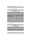
Removal and Replacement Procedures
Section Description
# of Screws Removed
5.14 Display Assembly
Display bezel
Camera module
Display inverter
Display panel
Display hinges
Display hinge covers
Wireless antenna transceivers
Microphones
Camera cable
6
5
0
0
6
4
0
4
0
0
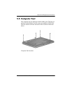
5.15 Top Cover 18
5.16 Wireless Switch Board 2
5.17 Audio Board 1
5.18 Bluetooth Module 2
5.19 USB/Magnetic Board 1
5.20 ExpressCard Assembly 4
5.21 Top Cover Support Trim 5
5.22 Display Lid Switch Module 0
5.23 Power Connector Assembly 2 to remove the power
connector assembly bracket
1 to remove the USB board
1 to remove the power
connector assembly
5.24 System Board 7
5.25 Fan/Heat Sink Assembly 7 loosened
5.26 Processor 1 loosened
Disassembly Sequence Chart
(Continued)