


5–68 Maintenance and Service Guide
Removal and Replacement Procedures
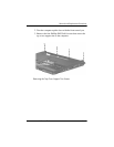
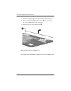
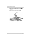
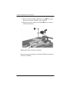
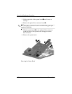
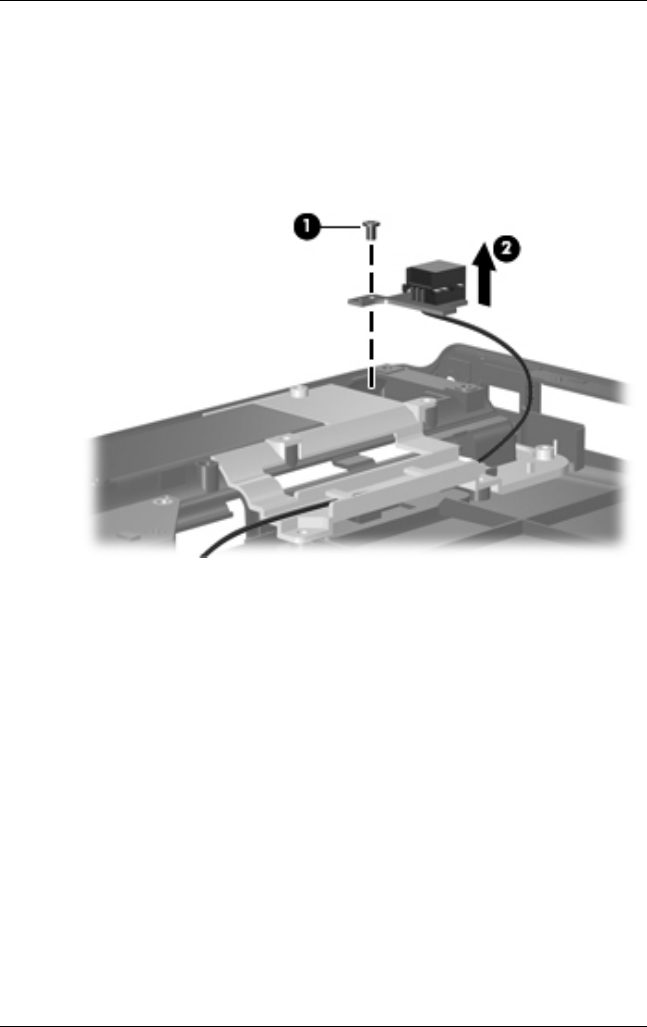
7. Remove the black Phillips PM2.5×5.0 screw 1 that secures
the power connector assembly to the computer.
8. Remove the power connector assembly 2 from its location
in the base enclosure.
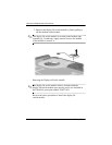
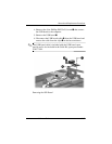
Releasing the Power Connector Assembly
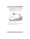
Reverse the above procedure to install the USB board and power
connector assembly.