


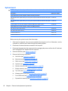

Fan/heat sink assembly
NOTE: All fan/heat sink assembly spare kits include replacement thermal material.
Description Spare part number
For use only with computer models using Intel processors:
Equipped with discrete video system memory 448016-001
Equipped with UMA video system memory 450934-001
For use only with computer models using AMD processors:
Equipped with UMA video system memory 450863-001
Equipped with discrete video system memory 450864-001
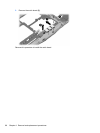
NOTE: When replacing the fan/heat sink assembly, be sure that the display switch module is removed
from the defective fan/heat sink assembly and installed on the replacement fan/heat sink assembly. See
Display switch module on page 89 for display switch module removal and spare part number information.
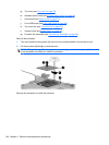
NOTE: To properly ventilate the computer, allow at least a 7.6-cm (3-inch) clearance on the right side
and rear panel of the computer. The computer uses an electric fan for ventilation. The fan is controlled
by a temperature sensor and is designed to turn on automatically when high temperature conditions
exist. These conditions are affected by high external temperatures, system power consumption, power
management/battery conservation configurations, battery fast charging, and software applications.
Exhaust air is displaced through the ventilation grill located on the left side of the computer.
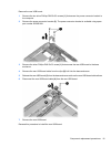
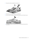
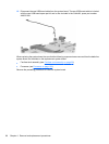
Before removing the fan/heat sink assembly, follow these steps:
1. Shut down the computer. If you are unsure whether the computer is off or in Hibernation, turn the
computer on, and then shut it down through the operating system.
2. Disconnect all external devices connected to the computer.
3. Disconnect the power from the computer by first unplugging the power cord from the AC outlet and
then unplugging the AC adapter from the computer.
4. Remove the battery (see
Battery on page 47).
5. Remove the following components:
a. Hard drive (see
Hard drive on page 52)
b. Optical drive (see
Optical drive on page 59)
c. Switch cover (see
Switch cover on page 61)
d. Keyboard (see
Keyboard on page 63)
e. Speaker assembly (see
Speaker assembly on page 66)
f. Display assembly (see
Display assembly on page 69)
g. Top cover (see
Top cover on page 75)
h. Wireless switch board (see
Wireless switch board on page 80)
Component replacement procedures 99