


Camera module
NOTE: If it has been determined that the camera module is the component that must be replaced to
complete the computer repair, the display assembly does not have to be removed. Follow the procedures
in this section to replace the camera module. For information on replacing the display assembly and
other display assembly internal components, see
Display assembly on page 69.
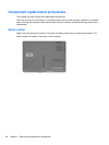
Description Spare part number
Camera module (includes 2-sided tape) 448002-001
Before removing the camera module, follow these steps:
1. Shut down the computer. If you are unsure whether the computer is off or in Hibernation, turn the
computer on, and then shut it down through the operating system.
2. Disconnect all external devices connected to the computer.
3. Disconnect the power from the computer by first unplugging the power cord from the AC outlet and
then unplugging the AC adapter from the computer.
4. Remove the battery (see
Battery on page 47).
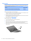
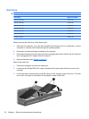
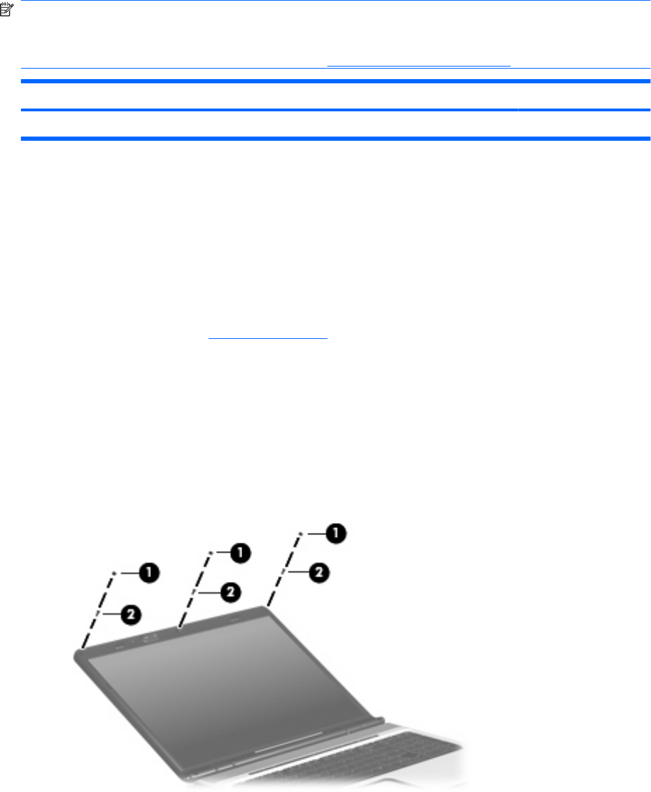
Remove the camera module:
1. Turn the computer display-side up, with the front toward you.
2. Open the computer as far as possible.
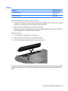
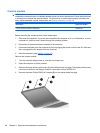
3. Remove the three rubber screw covers (1) on the display bezel top edge. The display rubber screw
covers are included in the Display Screw Kit, spare part number 432967-001.
4. Remove the three Phillips PM2.5×8.0 screws (2) on the display bezel top edge.
48 Chapter 4 Removal and replacement procedures