


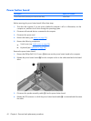
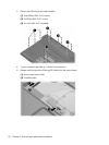
6.
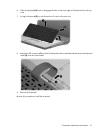
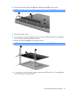
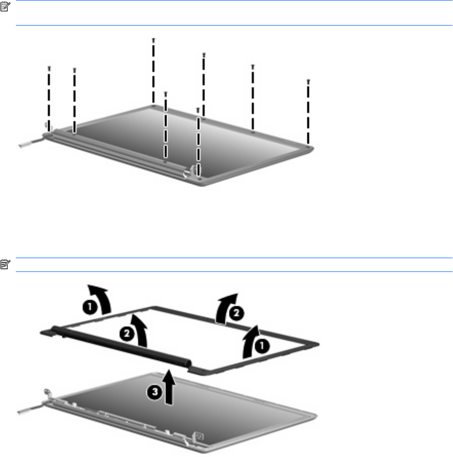
Remove the eight Phillips PM2.5×7.0 screws that secure the display bezel to the display assembly.
NOTE: All screws used to secure display assembly internal subcomponents are available in the
Display Screw Kit, spare part number 431400-001.
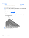
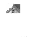
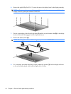
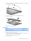
7. Flex the inside edges of the left and right sides (1) and the top and bottom sides (2) of the display
bezel until the bezel disengages from the display enclosure.
8. Remove the display bezel (3).
NOTE: The display bezel is available using spare part number 453525-001.
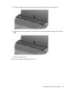
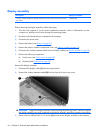
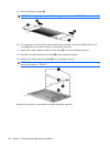
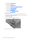
9. If it is necessary to replace the display inverter, release the inverter (1) from the display enclosure
as far as the display panel cable and backlight cable will allow.
46 Chapter 4 Removal and replacement procedures