


5–4 Maintenance and Service Guide
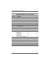
Removal and Replacement Procedures
Section Description
# of Screws Removed
5.10 Keyboard 3
5.11 RTC Battery 0
5.12 Internal Memory Module 0
5.13 Modem Module 2
5.14 Mini Card WWAN Module 2
5.15 Switch Cover 6
5.16 Power Button Board 2
5.17 Fan Assembly 1
5.18 Heat Sink 6 loosened
5.19 Processor 1 loosened
5.20 Display Assembly
Display bezel
Display hinges
Display panel
Display inverter
Wireless antenna transceivers
7
4
4
6
0
2
5.21 Top Cover 12
5.22 PC Card/Digital Media Board 3
5.23 Speaker 0
5.24 Microphone 0
5.25 System Board 6
5.26 MultiBay II Eject Assembly 1
Disassembly Sequence Chart
(Continued)