


2-9
Installing the Series 8200zl Switch
Installation Procedures
Installing the Series 8200zl
Switch
Installation Location
Before installing the switch, plan its location and orientation relative to other
devices and equipment:
■ In the front of the switch, allow at least 7.6 cm (3 inches) of space for the
twisted-pair and fiber-optic cabling.
■ In the back of the switch, allow at least 10.2 cm (4 inches) of space for the
power cord and cooling.
■ On the sides of the switch, leave at least 7.6 cm (3 inches) for cooling.
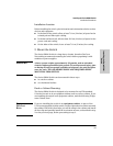
2. Mount the Switch
The Series 8200zl Switch is a large heavy chassis, therefore ProCurve
Networking recommends mounting the switch before populating it with
modules or power supplies.
WARNING A base system weighs approximately 50 pounds, and an unloaded
chassis weighs approximately 44 pounds. To avoid personal injury, plan
on having at least two people available to help move the unit into place
onto the rack. TWO OR MORE PEOPLE ARE REQUIRED WHEN
MOUNTING THIS SWITCH.
The Series 8200zl Switch can be mounted in these ways:
■ in a rack or cabinet
■ on a horizontal surface
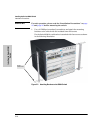
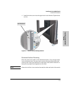
Rack or Cabinet Mounting
The Series 8200zl Switch is designed to be mounted in any EIA-standard
19-inch telco rack or in an equipment cabinet such as a server cabinet. If you
are installing the switch in an equipment cabinet, read the following “Equip-
ment Cabinet Note.”
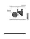
Equipment
Cabinet
Note
If you are installing the switch in an equipment cabinet, in place of the
12-24 screws supplied with the switch, use the clips and screws that came with
the cabinet. Plan which four holes you will be using in the cabinet and install
all four clips and partially install the two bottom screws, as described in step
2 on the previous page, before proceeding to step 3.