


2-17
Installing the Series 8200zl Switch
Installation Procedures
Installing the Series 8200zl
Switch
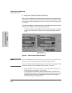
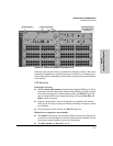
4. Install a Power Supply
The switch will run on one power supply. However, only the first six module
slots (A-F) will be powered when using only one power supply. In order to
power all 12 module slots there needs to be two power supplies installed in
the switch.
When there is two power supplies installed in the switch and one should fail,
the other power supply can keep the switch running and the first six module
slots operational.
Caution The Series 8200zl switch is designed to provide continuously operating PoE
power in the event of a single power supply failure with only a loss of PoE
power to lower priority ports.
If more than one power supply fails while the switch is at or near maximum
operating power (that is: the sum total of all PoE supply capacity minus the
largest supply, see chapter 2 and 4 of the PoE (ProCurve Power over Ethernet)
Devices Planning and Implementation Guide) loss of all PoE power may
result.
To return PoE power to the ports, without causing the switch to reboot, when
there are two or more power supplies still supplying 12V power, unplug the
power cord for 5 seconds and replug it for each power supply one at a time.
Another, load-sharing redundant power supply (either a ProCurve Switch zl
875 W Power Supply (J8712A), or a ProCurve Switch zl 1500 W Power Supply
(J8713A) can be installed in the back of the switch. The 8212zl can hold up to
four power supplies.
The 875 W Power Supply (J8712A) can supply up to 273 watts for PoE power.
The 1500 W Power Supply (J8713A) can supply up to 900 watts at 220 volts for
PoE power.
To prevent overloading of the building circuits breakers, the second power
supply can be connected to a different AC power source from the other supply.
This also helps with redundancy, if one AC power source fails, the switch will
continue to run.
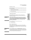
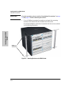
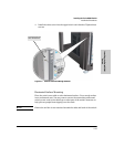
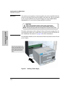
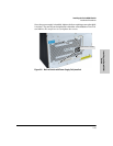
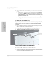
Install the second power supply into power slot number 2 as shown in Figure
2-3.
The slot cover can be removed with either a flat-bladed or Torx T-10 screw-
driver. Retain the slot cover for future use.