


• Memory mapped control and status registers (CSRs) control the cell for management needs.
• System management bus (SMBus) reads the processor module information EEPROM, scratch
EEPROM, and thermal sensing device.
• I2C bus reads PDH, cell, and cell power board FRU ID information.
• Serial presence detect (SPD) bus detects and investigates loaded DIMMs.
• Timing control of cell reset signals.
• Logic analyzer ports for access to important PDH signals.
• PDH resources accessible by the processors (system firmware) and the management
subsystem.
• Flash EPROM for system firmware bootstrap code storage and update capability.
• System firmware scratch pad SRAM for operation instruction and data storage.
• Battery backed NVRAM and real time clock (RTC) chip to provide wall clock time.
• Memory-mapped registers for configuration related information
• Console UARTs (moved from I/O space).
• Low level debug and general purpose debug ports (UART).
• Trusted platform monitor (TPM).
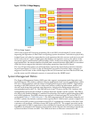
Reset
The sequencing and timing of reset signals is controlled by the LPM, a field-programmable gate
array (FPGA) that resides on the cell. The LPM is powered by the housekeeping rail and has a
clock input from the PDH daughter card that runs continuously at 8 MHz. This enables the LPM
and the rest of the utility subsystem interface to operate regardless of the power state of the cell.
Cell reset can be initiated from the following sources:
• Power enable of the cell (initial power-on)
• Backplane reset causes installed cells to reset, or cell reset initiated from PDHC in direct
response to an MP command or during a system firmware update
• System firmware-controlled soft reset initiated by writing into the PDH interface chip test
and reset register
The LPM contains a large timer that gates all the reset signals and ensures the proper signaling
sequence regardless of the source of that reset event. The most obvious reset sequencing event
is the enabling of power to the cell, but the sequencing of the reset signals is consistent even if
the source of that reset is an MP command reset for the main backplane, a partition, or the cell
itself.
Cell OL*
For online add (OLA) of a cell, the CC goes through the normal power on reset sequence. For
online delete (OLD) of a cell, software cleans up to the I/O (SBA) interface to put it in reset mode
and hold it there. When the I/O (SBA) link is held in reset, the cell is ready; power can be turned
off and the cell can be removed.
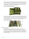
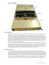
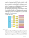
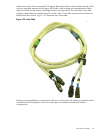
I/O Subsystem
The SIOBP is an update of the GXIOB, with a new set of chips that increase the board’s internal
bandwidth and support the newer PCI-X 2.0 protocol. The SIOBP uses most of the same
mechanical parts as the GXIOB. The connections between the I/O chassis and the rest of the
system have changed. The cell board to I/O backplane links are now multichannel, high-speed
serial (HSS) based rather than a parallel interface. Because of this, the SIOBP can only be paired
with the sx2000 cell board and is not backward compatible with earlier Superdome cell boards.
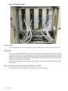
The term PCI-X I/O chassis refers to the assembly containing an SIOBP. All slots are capable of
supporting both PCI and PCI-X cards.
I/O Subsystem 37