


Installation 14
2.
Connect the negative (black) lead to the negative battery terminal.
NOTE: A small amount of arcing may occur when connecting the batteries. This is normal and does not
damage the unit or present any safety concern.
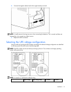
3. Replace the UPS front bezel.
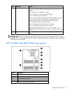
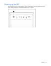
Selecting the UPS voltage configuration
Using a small tool, position the DIP switches according to the desired voltage configuration as identified
on the rear panel of the UPS and in the following table.
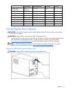
NOTE: The DIP switches must be set before powering up the unit. The unit does not change operating
modes while powered up.
NOTE: An asterisk (*) indicates the default setting.
Output voltage Input voltage range DIP switch 2 DIP switch 1