


Chapter 4
Peripherals and Accessories
4-116 HP e3000 Business Servers Configuration Guide – Effective 1/04
Information Subject to Change
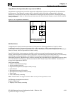
GBIC (VA7100 only)
A Gigabit Interface Converter (GBIC) is connected to each array controller as a transceiver for data and to
convert the data from an optical signal to an electrical signal and vice versa. Each VAP includes a single GBIC.
Based on user configurations, additional GBICs may be required. Only the GBICs A6203A (Enterprise) and
A6241A (Commercial) are supported with the VA7100. These are Finisar GBICs, which provide readable serial
number functionality.
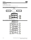
Redundant Power Supply and Fan Modules
The array is shipped with two fully redundant power/fan modules. Each power/fan module contains:
• One load-sharing power supply which works in conjunction with the second power supply. The power
supplies share the power load reciprocally; one supply automatically increases its output to compensate for
reduced output from the other. If one power supply fails, the other supply delivers the entire load to
maintain power for the array. If both power supplies fail, the controller will shutdown the array. Each
power supply uses a separate power cord. Both power supplies can be plugged into a common power
source, but it is recommended that each supply be plugged into a separate circuit to provide power source
redundancy.
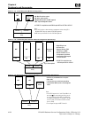
• Two internal fan modules provide cooling airflow and maintain the proper operating temperature for the
entire array enclosure. If a fan fails, a fan fault will occur and the associated power supply will shut down.
The other power supply will continue to operate and its associated fans will continue to cool the array.
Also, if one power supply fails, both of its associated fans will continue to operate to cool the array.
Note: During normal operation, if a failed power supply/fan module is removed, it must be replaced within
two minutes to maintain proper cooling of the array. If a power/fan module slot is left empty, the airflow
path will be disrupted and the array will overheat.
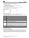
Midplane
The midplane, internal to the array enclosure, contains the following features for the identification of the array.
This information is stored into redundant EEPROMs during the manufacturing process:
Item Description
World Wide Name (WWN) The Node WWN is used by the OS drivers to identify the array enclosure.
Default Fibre Channel Loop
Addresses
The following default Fibre Channel loop addresses are assigned to array controllers: Array Controller 1: 108 Array
Controller 2: 110
The default Fibre Channel loop addresses can be changed using either the Virtual Front Panel (VPF) or the Command Line
User Interface (CLUI) included with your HP Command View SDM software.
NOTE: An array in a point-to-point configuration does not arbitrate for the bus, so no Fibre Channel loop addresses are required.
Product Mode Parameters Retains various operating parameters
Product Serial Number Same as the serial number sticker applied to the array
Product ID Number VA7100 Same as the product ID number (A6188A)
Product ID Number VA7110 Same as the product ID number (A7293A)
Product ID Number VA7410 Same the product ID number (A6218A)
User installed licenses are stored within the Midplane EEPROM. These licenses are associated with a
particular product serial number. If the Midplane must be replaced, a special Midplane may be ordered which,
will allow the automatic regeneration of product serial number, licenses and product mode parameters. This
information will be automatically re-programmed within the new Midplane EEPROMs if the replacement
procedure is followed.
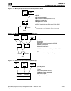
LED Status Indications
If a disk drive, controller, battery, DIMM, power supply or fan fails in the enclosure, a fault will be indicated by
a fault (amber) LED on the module. The nature of the fault can be localized by examining the state of the
LEDs.