


22 Chapter1
Addendum to D Class Enterprise Servers System Installation Guide
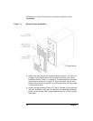
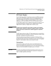
DC Power Supply
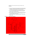
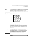
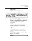
Table 1-2 shows the pinouts for the site end of this cable. Figure 1-5
shows a diagram of the pins. The user/installer must make connections
to the site installation using this information. Connect the 9-pin
connector on the supplied cable to the negative 48/60 volt power supply
at the rear of the system ch assis.
WARNING 1.) The power supply cable is used as the main disconnect device
for this equipment. The key switch on front of SPU does NOT
disconnect the input to power suppl y.
2.) Make sure that all central office s afety p recautions are
carefully observed when c onnecting the power supply to
primary power source.
3.) This product is to be installed only in Restricted Access Areas
(dedicated equipment rooms, equipment closets or the like) in
accordance with Articles 110-16 to 110-18 of National Electrical
Code, ANSI/NFFA 70.
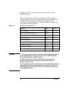
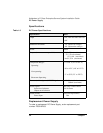
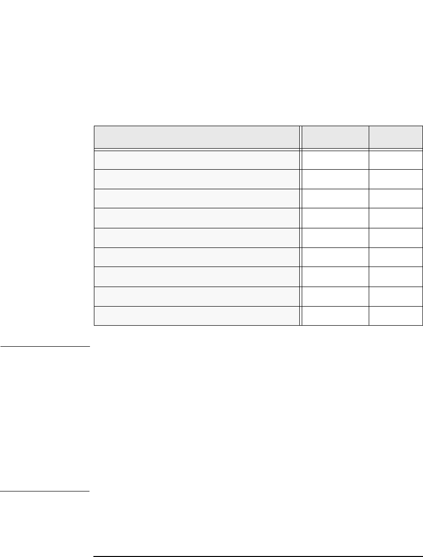
Table 1-2 DC Power Cable Pinouts
Function Color Pin No
-48V (14 AWG) Black 1
Power Supply Status (Open-OK) White 2
Shield 3
-48V (14 AWG) Black 4
Fan Status (Open-OK Red 5
Alarm Common Green 6
-48V RTN (14 AWG) Red 7
-48V RTN (14 AWG) Red 8
Remote Reset (Close-reset) Black 9