


Index–4 Maintenance and Service Guide
Index
parallel port, enabling/disabling 5–7
password clearing
4–5
password policy
5–4
password, changing
5–4
pen holder
2–9, 2–10
plastic parts, service considerations
4–1
Plastics Kit
contents
3–9
spare part number
3–4, 3–9, 3–14
pointing device components
2–6
pointing stick
2–6
pointing stick button
2–6
ports
1394
2–8
external monitor
2–11
monitor
2–11
USB
2–8, 2–9, 2–10
power connector
2–11
power cord
set requirements
10–1
spare part numbers
3–10, 3–12
power light
2–5
power switch
2–7
presentation button
2–3
R
rear components 2–11
recovering information
8–5
recovery tools
8–3
recovery, performing
8–2
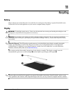
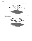
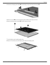
recycling
battery
11–1
display components
11–1
right-side components
2–8
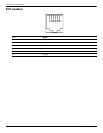
RJ-11 jack
connector pinout
9–4
location
2–11
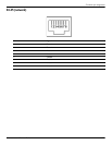
RJ-45 jack
connector pinout
9–5
location
2–11
rotate button
2–11
RTC battery
removal
4–23
spare part number
3–4, 3–11, 4–23
Rubber Kit, spare part number
3–4, 3–14
S
Screw Kit
contents
3–10
spare part number
3–10, 3–14
screw listing
7–1
SD Card Reader
2–8
security cable slot
2–8
security level, setting
5–7
security menu
5–4
serial number
3–1, 4–6
serial port, enabling/disabling
5–7
service considerations
cables
4–1
connectors
4–1
overview
4–1
plastic parts
4–1
setup BIOS administrator password
5–4
Shield Kit, spare part number
3–4, 3–14
Smart card reader
2–10
Smart Card slot, enabling/disabling
5–7
solid-state drive
illustrated
3–8
precautions
4–2
removal
4–10
spare part number
3–6, 3–8, 3–12, 4–10
speaker
location
2–12
removal
4–26
spare part number
3–4, 3–14, 4–26
switch components
2–3
system board
removal
4–30
spare part numbers
3–4, 3–12, 4–30
system configuration menu
5–5
system diagnostics menu
5–5
system IDs
5–4
system Information
5–3
T
Terminal Emulation Mode 5–7
tools required
4–1
top components
2–1
top cover
removal
4–21
spare part number
3–4, 3–14, 4–21
TouchPad
2–6
TouchPad button
2–6
TouchPad light
2–5, 2–6
TouchPad on/off control
2–6
TouchPad scroll zone
2–6
TPM embedded security
5–4
transporting guidelines
4–3
U
Unconfigure AMT on Next Boot 5–7
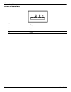
Universal Serial Bus (USB) port
connector pinout
9–6
enabling/disabling
5–7
location
2–8, 2–9, 2–10
unknown password
4–5