


CHAPTER 3 WIRING, CONNECTING
8
3.3 Wiring note
1.Installing the cable to Network connector must be done after checking the power supply off and “POW”
LED is “OFF”.
2.Wiring should not have bare cables exposed between connector contacts.
3.Network cables should be fixed without tension. Cables fixed under tension have potential of causing a
communication fault by to be removed a connector.
4.A terminating resistor is not built-in the unit. Please use the accessory of Bus resister(120
Ω
).
5.Ensure external emergency stop measures are taken to stop the inverter, in the event of a network fault.
(a) Remove the Power supply of the Inverter when the network master detects a communication fault.
(b) When the master detects a communication fault, turn on the intelligent input terminal which would be
allocated (FRS), (RS) and/or (EXT) function.
(c) Setting command P045 to except “02”.
In this setting, the inverter is tripped, deceleration or free run stop when it detects a communication
fault itself. (Factory initialization of command P045 is trip after deceleration stop (code: 01).)
See “4.2 Setting of the Inverter”.
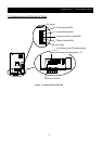
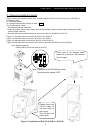
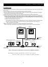
6.Basic components for construction of CANopen application are shown bellow.
Refer to the master’s description manuals when CANopen Network system comes into operation.
HITACHI
SJ200-2
SJ200-2
Terminating
Resistor (120Ω)
Terminating
resistor
(120Ω)
Multi port Tap
Other slave units
Power
Supply
DC24V
CANopen Master UNIT
(PLC)
Trunk line
Trunk line
Drop
line
Multiple Node branching drop line.
Figure 3-2 Example of components for construction of CANopen application
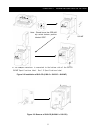
Configurater (PC)
HITACHI
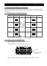
Note:Communication power supply(DC 24V) of SJ2-CO is not required.
Please don’t make a short circuit between PIN 1(Black) and 5(Red).
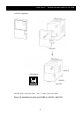
Terminating
resistor
(120Ω)