


13
Chapter 4 WIRING AND CONNECTION
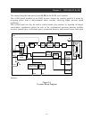
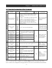
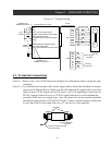
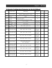
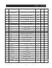
4.2 Function Explanation of the Terminals
Terminal Code Function
Common
terminal
electrical
specifications
Pulse train position
command inputs
SAP
SAN
SBP
SBN
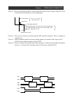
Pulse train position command input (see page 16)
• Mode 0 : 90 degree phase difference pulse
(quadrature)
• Mode 1 : Forward/Reverse signal; pulse train
• Mode 2 : Forward pulse/Reverse pulse
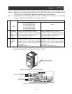
Built-in 150 ohm termination resistance can be
turned ON or OFF with DIP switch SWR.
Mode is selected via the pulse mode selection
parameter (P013)
DC 5V receiver in
p
ut
(based on RS-422
standard)
Encoder signal
inputs
EAP
EAN
EBP
EBN
EZP
EZN
A, B, Z: rotary encoder signal input
Photo coupler input
(Compatible with the
DC5V line driver
type rotary encoder)
Pulse train position
command input
permissive signal
(Note 1)
STAT
Position control with pulse train input
is valid when STAT is Turned ON.
(Note 3)
Orientation signal:
(Note 1)
ORT
Turn ON for orientation operation.
(Note 3)
LAD cancel signal:
(Note 1)
LAC
Turn ON to cancel LAD.
(Note 3)
Input terminals
Position deviation
clear signal:
(Note 1)
PCLR
Turn ON to clear position deviation
counter. (Note 3)
CM1
Photo coupler input
(Configure to an
inverter intelligent
input terminal.)
Encoder signal
output
AP
AN
BP
BN
Retransmits the input encoder signal (ratio 1:1).
DC5V line driver
output (based on
RS-422 standard)
Power supply for
encoder
EP5 DC +5V power supply EG5 150mA max
Positioning
completion signal
(Note 2)
POK
Used for position control or
orientation.
Output ON when the position comes
within the specified range (P017).
(Note 3)
Speed deviation
excessive signal
(Note 2)
DSE
Output ON when the real rotation
speed deviation from command speed
exceeds (P027). (Note 3)
Output terminals
Zero speed signal
(note 2)
ZS
Output when the real rotation speed
becomes zero speed detection level
(C063). (Note 3)
CM2
Open collector
outputs
(Configure to an
inverter intelligent
output terminal)
(Note 1): Valid when LAC is assigned to an intelligent input terminal of the inverter (SJ300).
(Note 2): Valid when POK is assigned to an intelligent output terminal of the main body (SJ300).
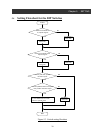
(Note 3): Refer to the configuration setting procedure for the inverter in the SJ300 Instruction Manual