


26
Chapter 7 FUNCTIONS
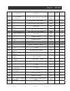
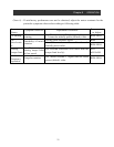
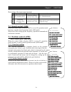
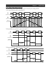
Data setting of the input-output terminal
Input-output terminal Terminal assignment Contents
Input
ORT terminal (ORT)
Set up 45 to one of
them of C001∼C008
ON : Orientation mode
Output
Positioning
completion signal
(POK)
Set up 23 to one of
them of C021∼C025
Output when it comes to the positioning
completion range.
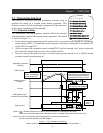
7.2 Speed control (ASR)
A044: 1
st
Control method
P012: Control mode selection
A001: Frequency command selection
A002: Operation command selection
F001: Frequency setting
F002: Acceleration time
F003: Deceleration time
F004: Operation direction selection
H002/H202-H052/H252:
Motor constant relation data
When the control mode selection (P012) is set to 00, operation mode
becomes a speed control operation mode (ASR mode).
Relation
Please drive after setting up the frequency, operation command and
each motor constant .
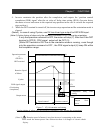
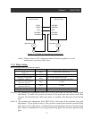
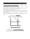
7.3 Position control (APR)
(Electronic gear function)
When the control mode selection (P012) is set to 01, operation
mode becomes a speed control operation mode (APR mode).
7.3.1 Function outline
A044: 1
st
Control method
P012: Control mode selection
A002: Operation command selection
P017: Completion range setting
P018: Completion delay time
P019: Electronic gear position selection
P020: Electronic gear ratio numerator
P021: Electronic gear ratio denominator
P022: Feed forward gain
P023: Position loop gain
C001-C008: Intelligent input terminal
C021-C025: Intelligent output terminal
H002/H202-H052/H252:
Motor constant relation data
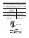
This function generates the frequency based on the position
command pulse which comes from the pulse train input from the
terminal and position feed back pulse which is detected by the motor
encoder, and performs the position control operation. It can be used
as synchronous operation of main and sub motor. Also the turn
ratio of main and sub motor can be changed by setting up the
electronic gear ratio (N/D). (Electronic gear function)
Relation
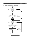
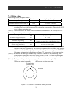
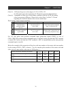
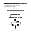
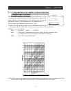
7.3.2 Control mode setting
Inverter at the main motor (master inverter) can be set both as a
speed control and position control. Please set up the inverter at the
sub motor side (slave inverter) to a position control mode.