


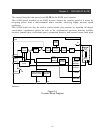
Chapter 4 WIRING AND CONNECTION
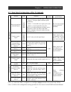
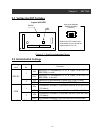
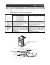
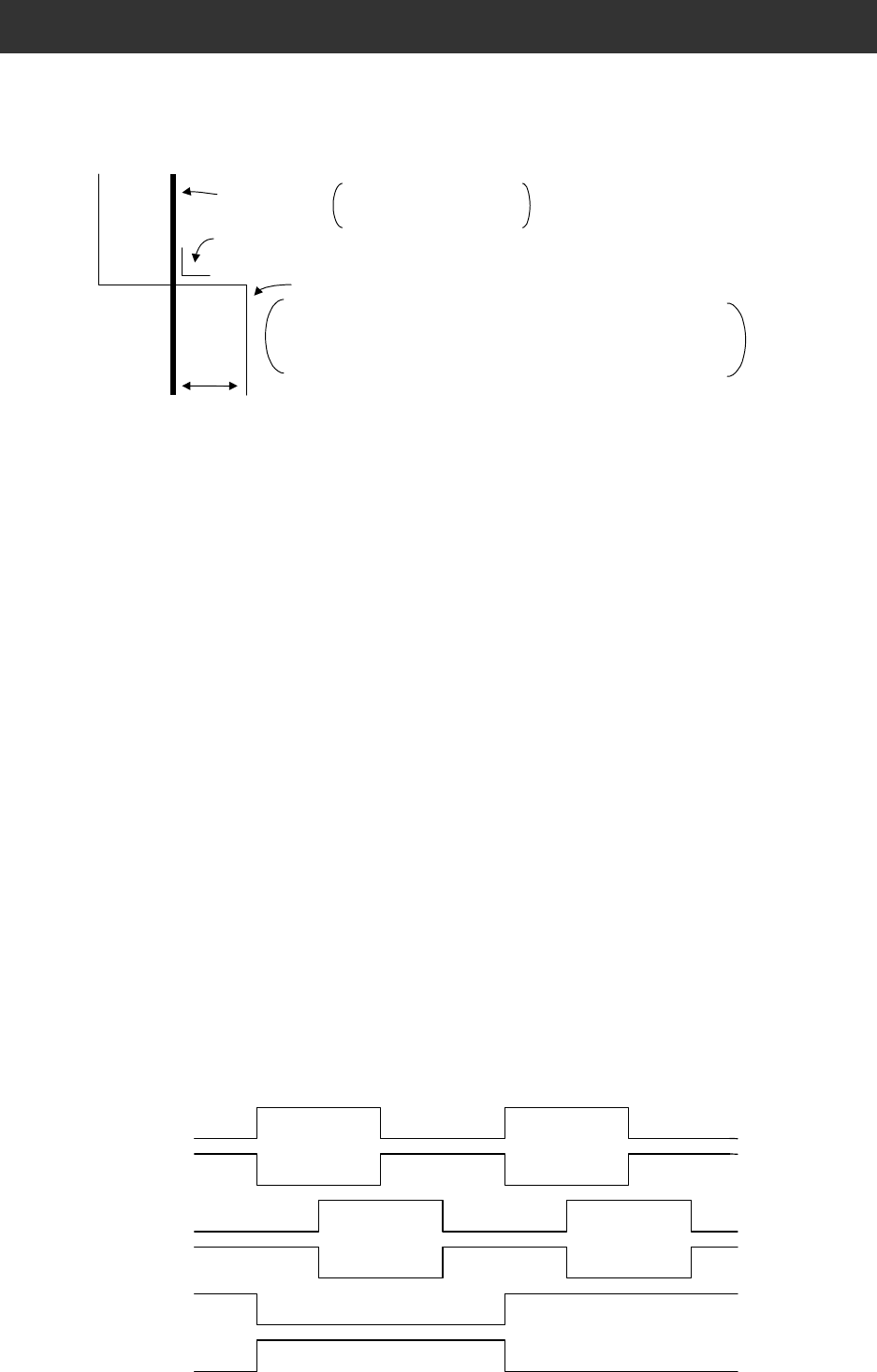
(Note 3) : Be sure to separate the power wiring from the control circuit wiring. If they have to be
crossed, be sure that they cross at a right angle.
Power cables
R, S, T, U, V, W, P, PD,
RB, N, R0, T0 etc.
Right angle
Input/Output signal lines
Control signals (STAT, ORT, LAC, PCLR, SAP, SAN, SBP, SBN,
EAP, EAN, EBP, EBN, POK, DSE, ZS, AP, AN, BP, BN, L, EP5,
EG5, CM1, CM2, P24, PLC etc.)
Separate 10cm or more.
(Note 4) : Take care not to short circuit between the EP5 and EG5 terminals. There is a danger of
malfunction.
(Note 5) : Isolate common signal for inverter analog signals (L terminal of the logic card of
SJ300) from common terminal of the SJ-FB.
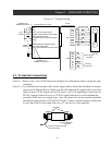
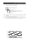
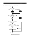
(Note 6) : Be sure to connect the encoder signal lines properly so that the relationship among their
phases is as shown below during rotation of the motor (Standard EG5).
15
EAP
EAN
EBP
EBN
EZP
EZN