


14
Chapter 4 WIRING AND CONNECTION
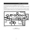
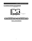
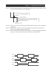
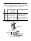
Figure 4-2 Terminal wiring
H
O
L
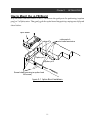
SJ-FB
(Feed-back board)
Inverter main body control
Configure to an
intelligent input term. 1-8
EP5
EG5
EAP
EAN
EBP
EBN
EZP
EZN
M
EC
Motor with
encoder
SAP
SAN
SBP
SBN
Pulse train pos.
command
POK Positioning completion signal
ZS Zero speed signal
DSE Speed deviation excessive signal
Output
terminal
FW
RV
LAC LAD cancellation signal
PCLR Position deviation Clear signal
ORT Orientation signal
CM1
Input
terminal
Configure to an
intelligent output term. 1-5
A
P
A
N
BP
BN
Encoder
signal output
STATPulse train input permisive signal
Encoder signal
TM1
TM2
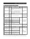
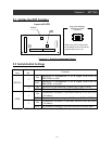
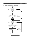
4.3 Terminal Connections
(Note 1) : Please refer to the SJ300 Instruction Manual for information about wiring the logic
terminals.
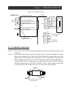
(Note 2) : Use a shielded, twisted pair cable for the signal cables, and cut the shielded covering as
shown in the diagram below. Make sure that the length of the signal cable is no more
than 20 meters. If the length exceeds 20 meters, use a VX application control device
RCD-E (remote control device) or CVD-E (signal isolation) to avoid malfunction
caused by EMC noise or voltage drop. Also, the signal wire for the encoder should be
shielded twisted pair line of 28 AWG (0.75mm
2)
or more, and the distance should also
be less than 20m. If more than 20m, use a 5V line driver relay amplifier.
DO NOT GROUND
THIS END
Connect to common terminal
of the option board.
Insulation