


2-2 Architecture and Components
Hitachi Universal Storage Platform V/VM User and Reference Guide
Hardware Architecture
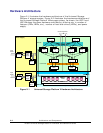
Figure 2-1 illustrates the hardware architecture of the Universal Storage
Platform V storage system.
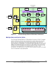
Figure 2-2 illustrates the hardware architecture of
the Universal Storage Platform VM storage system. As shown, the USP V and
USP VM share the same hardware architecture, differing only in number of
features (FEDs, BEDs, etc.), number of hard disk drives (HDDs), and power
supply.
DKA
DKA
DKA
FED
DKA
DKA
DKA
BED
DKA
DKA
DKA
FED
DKA
DKA
DKA
BED
CSW
CSW
CSW
CSW
CACHE
CMA
CACHE
CMA
SMA SMA
Channel Interface
FC-AL (4 Gbps/port)
Cache Path
SM Path
Max. 48
HDDs
Disk Unit
Battery
Box
Battery
Box
Controller
Power Supply
Max. 1,152 HDDs per storage system
Disk Path (max. 64 paths)
Input
Power
AC-Box
AC-Box
AC-DC
Power
Supply
Input
Power
AC-Box
AC-Box
AC-DC
Power
Supply
AC-DC
Power
Supply
Power Supply
AC-DC
Power
Supply
Battery
Box
Battery
Box
Figure 2-1 Universal Storage Platform V Hardware Architecture