


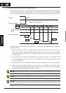
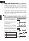
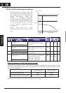
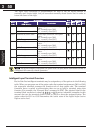
DC Bus AVR for Deceleration Settings
This function is to achieve stable DC
bus voltage in case of deceleration. DC
bus voltage rises due to regeneration
during deceleration. When this
function is activated (B133=01),
inverter controls the deceleration time
so that the DC bus voltage not to go up
to the overvoltage trip level, and leads
to the trip-less operation during
deceleration.
Please note that the actual
deceleration time may be longer in this
case.
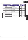
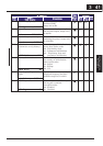
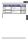
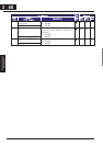
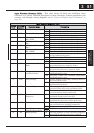
“B” Function Defaults
Func.
Code
Name /
SRW Display
Description
Run
Mode
Edit
-FE
(EU)
-FU
(USA)
Units
DC bus AVR for decel.
P-gain
B055
VpnP 0000.2s
Proportional gain adjustment for
DC bus AVR function. Range is:
0.2 to 5.0
9
0.2 0.2
DC bus AVR for decel.
I-time
B056
VpnI 0000.2s
Integration time adjustment for
DC bus AVR function. Range is:
0.0 to 150.0
9
0.2 0.2 sec
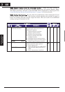
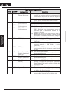
DC bus AVR selectionB133
Vpn AVR OFF
00}Disabled
01}Enabled
U
00 00
Threshold voltage of DC bus
AVR setting
B134
Vpn LVL 00380V
Setting of threshold voltage of
DC bus voltage to start DC bus
AVR function. Range is:
200V class}330 to 395
400V class}660 to 790
U
380
/760
380
/760
V
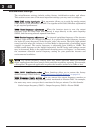
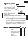
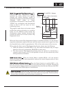
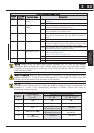
Difference between OV LAD STOP and DC bus AVR
This function is similar to OV LAD STOP (B130,B131) from the OV trip-less point of view.
The DC bus AVR has the higher priority when both OV LAD STOP function and DC bus AVR
function is set enabled.
OV LAD STOP DC bus AVR
Actual deceleration time Short Long
Fluctuation of the DC bus voltage Big Small
Please select the suitable function according to your system.
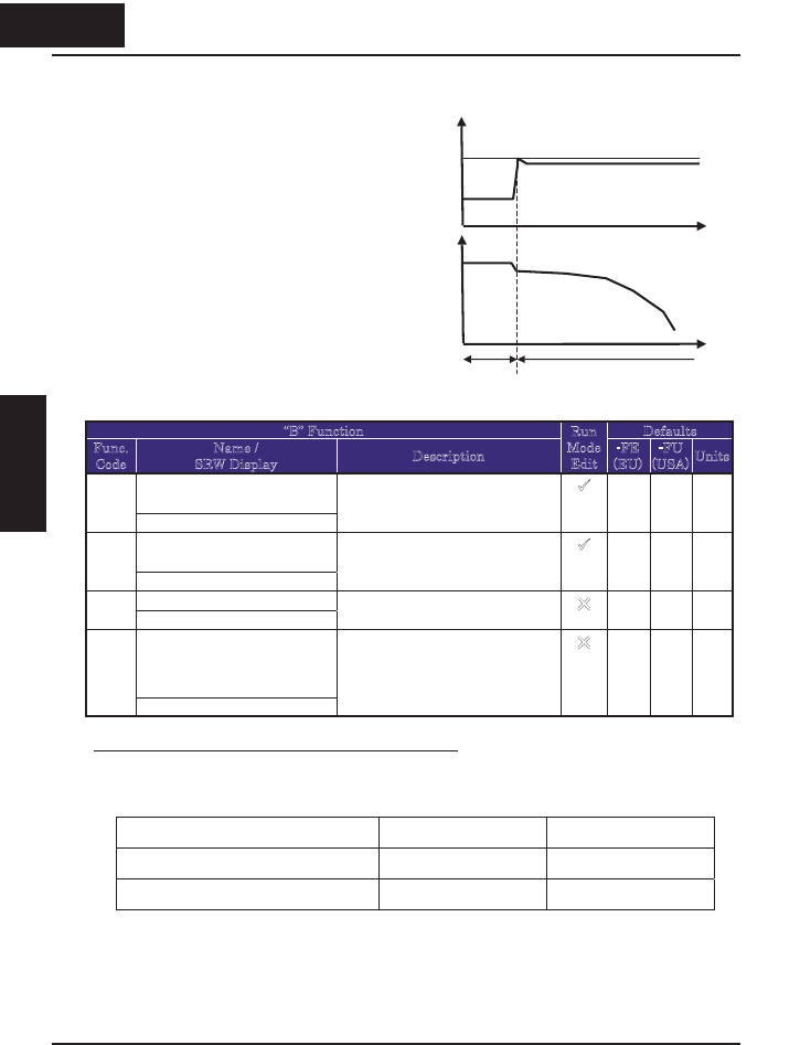
Threshold voltage to start DC bus AVR (B134)
DC bus AVR
t
t
DC bus voltage
Freq
Normal
operation
Configuring Drive
Parameters
346
3 46
&RQ¿JXULQJ'ULYH
Parameters