


36
SCANNER OPERATION
INDICATOR DESCRIPTIONS
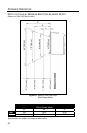
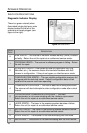
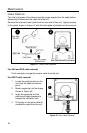
Diagnostic Indicator Display
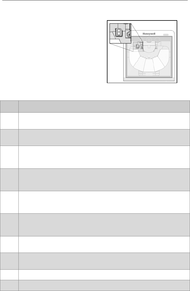
There is a green colored (when
illuminated) single digit error code
display located to the left of the
scanner’s mirrored polygon (see
figure to the right).
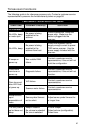
ERROR
CODE
DESCRIPTION
0
RAM ERROR – The scanner’s Random Access Memory (RAM) is tested
as faulty. Return the unit for repair at an authorized service center.
1
PROGRAM ERROR – The scanner’s software program is failing. Return
the unit for repair.
2
INTERFACE ERROR – After power up and any application exit (e.g.
MetroSet, etc.), the scanner checks the interface hardware with that
chosen in configuration. If they do not agree, an interface error exists.
3
CONFIGURATION ERROR – The non-volatile configuration memory did
not agree with the data last saved. Default configuration data is then
used and the scanner continues operating.
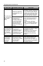
4
COMMUNICATION ERROR – The RS232 data line is being held active.
The scanner will abort attempts to enter configuration mode after a short
timeout.
5
COPROCESSOR COMMUNICATION ERROR – The main
microprocessor is not communicating with the interface coprocessor.
Return the unit for repair at an authorized service center.
6
LASER ERROR – The laser in the scanning system denotes a failure.
Return the unit for repair at an authorized service center.
7
MOTOR ERROR – The motor in the scanning system denotes a failure.
Return the unit for repair at an authorized service center.
8 SCALE ERROR – The scanner is not communicating with the scale.
9 EAS ERROR – The scanner is not communicating with the EAS device.
Figure 34. Failure LED