


WEB-700 WEB-700-O CP-700
95-7776—03 10
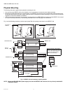
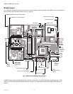
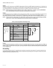
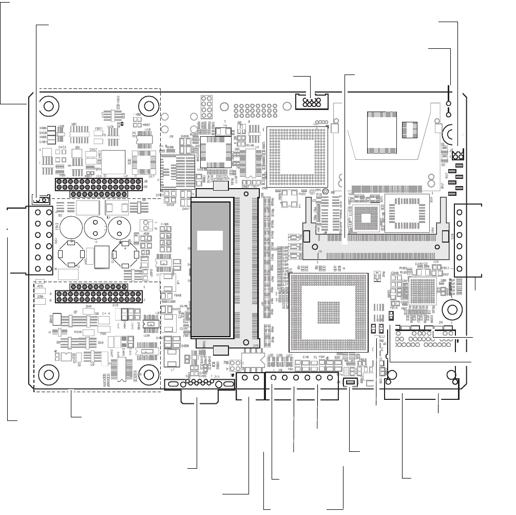
Board Layout
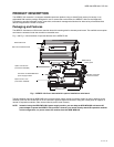
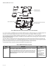
Fig. 5 shows the location of connectors, option slots, and other features of the main board in the WEB/CP-700. For side views of
communications ports and other features, see Fig. 6, page 13.
Fig. 5. WEB/CP-700 main board layout details
A WEB/CP-700 controller ships with both option card slots 1 and 2 open. The DDR-2 RAM socket is populated with a 1GB
module. A variety of communications option cards are available. For related details, see the next section About Expansion
Options.
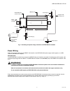
PS
-
OUT
PS + OUT
BB 12V
RS-485
-
RS-485 +
485 GND
PS +
PS
-
NiMH battery connector (keyed)
Earth grounding lug
LED header
Serial mode select jumper
Option card 2 area including socket header
MiniPCI socket
DDR-2
RAM
Option card 1
area including
socket header
RS-232 (DB-9) COM1
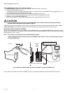
External 12V backup battery
GND
RS-485
support of
remote IO
modules
LEDs
LANn
Debug
LED
LAN1
Primary Ethernet
(RJ-45)
LAN2
Secondary
Ethernet
(RJ-45)
From
power
supply
module
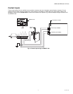
Contact Inputs
Door
tamper
UPS battery OK
UPS AC present
LEDs
status,
heartbt
Push-
button
SW1
GND
GND