


WEB-700 WEB-700-O CP-700
9 95-7776—03
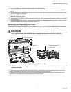
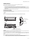
To mount on DIN rail
1. Securely install the DIN rail with at least two screws, near the two rail ends.
2. Position the NPB-PWR-UN-H power supply module on the rail, tilting to hook DIN rail tabs over one edge of the DIN rail
(Fig. 3).
3. Use a screwdriver to pry down the plastic locking clip, and push down and in on the module, to force the locking clip to snap
over the other edge of the DIN rail.
4. Mount the WEB/CP-700 controller onto the DIN rail in the same way, such that its left 6-position end connector faces the
NPB-PWR-UN-H power supply.
5. Slide the two devices together along the DIN rail to connect their 6-position connectors.
6. If installing any I/O expansion modules, repeat this for each one, until all are mounted on the DIN rail and firmly connected
into one assembly.
7. To keep the final assembly together, secure at both ends with DIN rail end-clips provided by the DIN rail vendor. This also
prevents the assembly from sliding on the DIN rail. See Fig. 3.
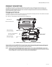
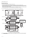
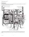
Removing and Replacing the Cover
You must remove the WEB/CP-700 cover to connect the battery (new unit), and/or to replace the NiMH battery, install any option
cards, or replace the NiMH battery. The cover snaps onto the base with four plastic end tabs–two on each end.
CAUTION
An LED ribbon cable connects the cover to the main board. Be careful when lifting the cover off. If the controller
is on a flat work surface, you can leave the cable connected, with the cover next to the unit. See Fig. 4.
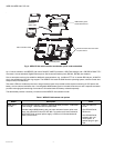
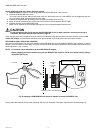
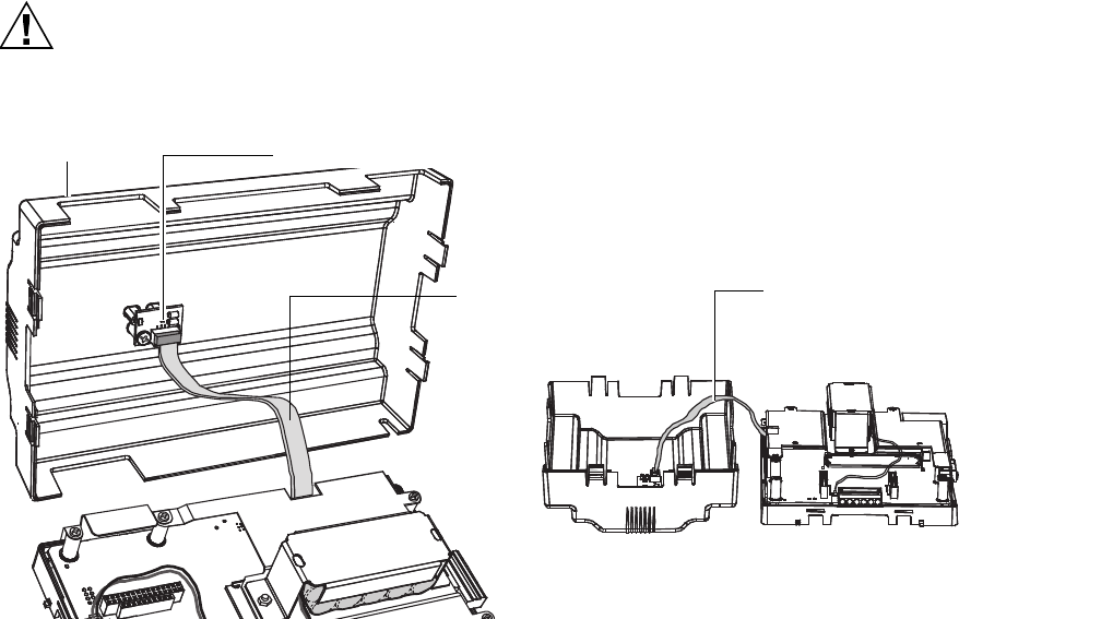
Fig. 4. Removing WEB/CP-700 cover.
NOTE: If accessory modules are plugged into the WEB/CP-700, you may need to slide them away from the unit to get to
the end cover tabs.
• To remove the cover, press in the tabs on both ends of the unit, and carefully lift it off (see previous Caution). If necessary,
unplug the LED cable from the cover, at the connector on the back of the cover (see Fig. 4).
• To replace the cover, make sure that the LED cable is connected and not folded outside the base. Orient the cover so the
cutout area for comm ports is correct, then push inwards to snap in place.
Cover
LED ribbon
cable
Connector for LED cable
LED cable left connected
between cover and
controller board