


WEB-700 WEB-700-O CP-700
13 95-7776—03
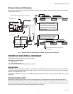
WIRING DETAILS
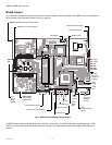
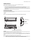
See Fig. 5, page 10 to locate connectors and other components on the WEB/CP-700 controller.
Make connections to the WEB/CP-700 in the following order.
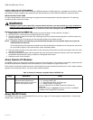
1. Install any option board (LON, RS-485, RS-232, etc.) in the available option slots. See Installing an Option Card, page 12
for a procedure. For complete details, refer to the specific documentation that accompanied the option.
2. Connect communications cables. See Communications Wiring, page 13 for ports available on the WEB/CP-700 base unit.
For ports on any installed option board (RS-232, LON, RS-485, modem) see the specific mounting and wiring guide for any
additional details.
3. Apply power to the unit. See Power Up and Initial Checkout, page 19.
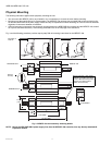
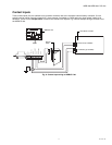
Communications Wiring
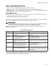
Communications ports on the WEB/CP-700 controller are primarily on the bottom side of the unit, with ports also on the right side
and top (Fig. 6). Communications port types include:
• Ethernet
•Serial
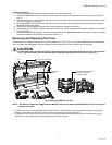
NOTE: Prior to connecting cables, provide strain relief for them to prevent damage to the controller.
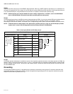
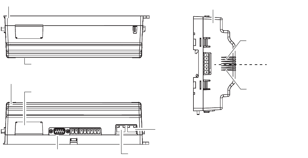
Fig. 6. WEB/CP-700 communications ports.
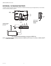
ETHERNET
Two, female 1-Gigabit Ethernet connections are provided on the WEB/CP-700. These are RJ-45 connectors labeled LAN1 and
LAN2. Use a standard Ethernet patch cable for connecting to a hub or Ethernet switch.
The factory-default IP address for LAN1 on a WEB/CP-700 is 192.168.1.12n, where the last numeral n in the address matches
the last digit in the WEB/CP-700’s serial number, and the subnet mask is 255.255.255.0.
By default, LAN2 on a WEB/CP-700 is
disabled.
Refer to the NiagaraAX Install and Startup Guide for details on changing IP address.
NOTE: Typically, you only use LAN1 (primary port), unless you have a specific application for the other LAN2 port. For
example, isolating a driver’s network traffic, using LAN2. Do not use LAN2 as the primary port.
Option slot 2 connector area
Option slot 1 connector area
RS-232 (DB-9) COM1
RS-485 COM2
15V PS -, + and
12V Backup Battery out
Bottom side
Right side
Top side
LAN 2 Ethernet (RJ-45)
LAN 1 Primary Ethernet (RJ-45)