


4
INTRODUCTION
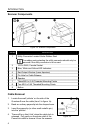
Scanner Components
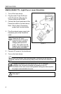
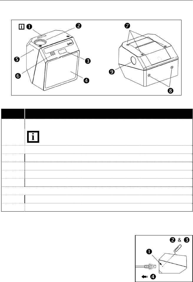
Figure 1a. Scanner Components
ITEM NO. DESCRIPTION
1 Utility Connector Located Under Rubber Seal
The rubber seal protecting the utility connector should only be
removed if the utility connector is to be used.
2 10-Pin RJ45, Female Socket
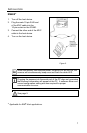
3 Blue, White and Yellow LED Indicators
4 Red Output Window (Laser Aperture)
5 Pin Hole for Cable Release
6 Speaker
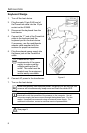
7 Three M2.5 x 0.45 Threaded Mounting Points
8 Two M2.5 x 0.45 Threaded Mounting Points
9 Button
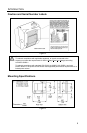
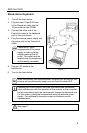
Cable Removal
1. Locate the small ‘pinhole’ on the side of the
QuantumE near the cable (item 5 in figure 1a).
2. Bend an ordinary paperclip into the shape shown.
3. Insert the paperclip (or other small metallic pin)
into the ‘pinhole’.
4. There will be a faint ‘click’ when the cable lock is
released. Pull gently on the strain-relief of the
PowerLink cable to remove it from the scanner.
Figure 1b.