


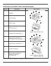
7
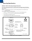
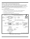
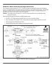
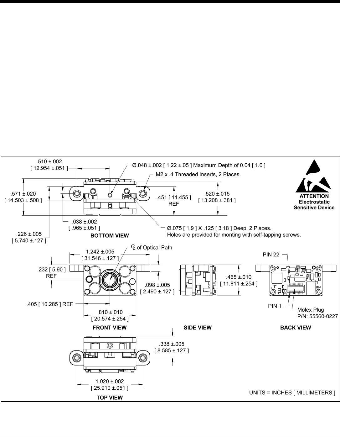
IS4910-02 / IS4911-02 Non-Decode Engine Dimensions
The -02 engine model includes two Ø .075" [1.9 mm] blind holes for mounting the engine with self-tapping
screws. Two additional M2 x .4 threaded inserts are provided as a secondary mounting option. The threaded
inserts are located on tabs that extend from the sides of the engine's chassis. A keying location point is
provided on the bottom of the engine to assist with alignment.
Warning: The limited warranty (on page 31) is void if the following guidelines are not adhered to when
mounting the engine.
When securing the engine by utilizing the two M2 threaded inserts:
• Use M2.2 x 4.5 Philips pan head, type AB, steel, zinc clear or equivalent screws.
• Do not exceeding 2.88 cm-kg [2.5 in-lb] of torque when securing the engine assembly to the host.
• Use a minimum mount thickness of 0.3 mm.
• Use safe ESD practices when handling and mounting the engine.
Figure 6. IS4910-02 / IS4911-02 Dimensions