


15
Snapshot Illumination Waveforms
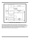
The following waveforms show how the illumination LEDs are controlled relative to the input signals
(Trigger and Illum_On) during the snapshot mode. The Trigger signal determines when the illumination and
image integrations begin. In addition, the duration of this signal determines the maximum integration and
illumination time. The Illum_On signal can be used in conjunction with the Trigger signal to ensure a minimum
amount of illumination.
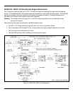
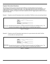
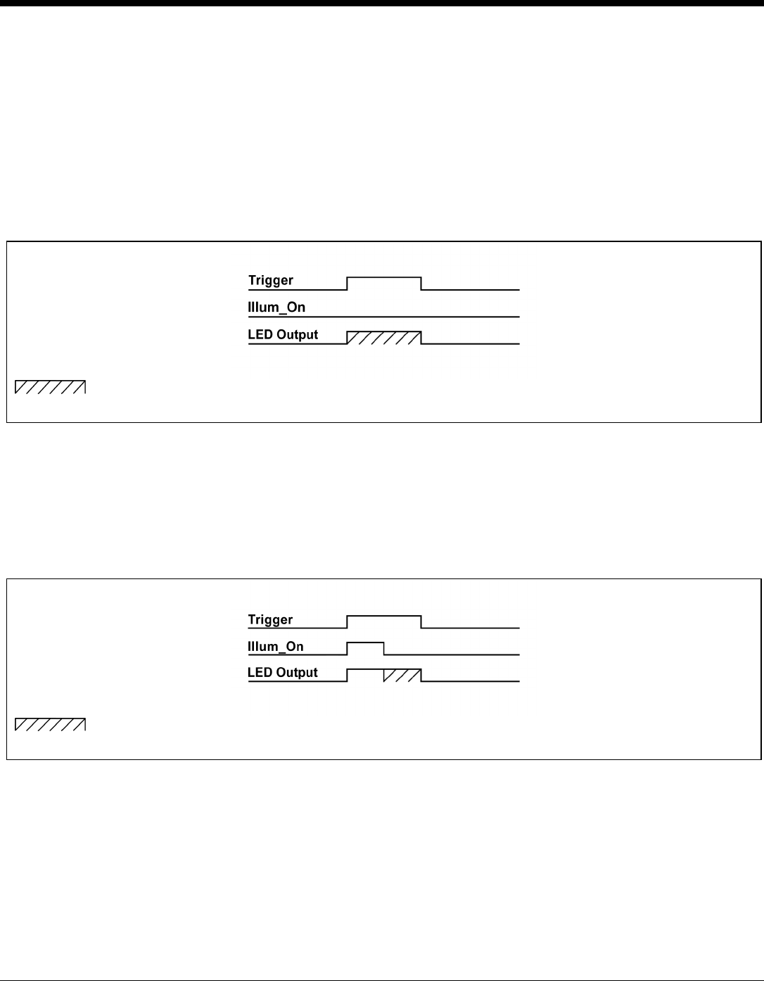
Example 1: Snapshot mode with Illumination duration controlled by FirstFlash circuitry only (see figure below).
= Denotes the actual duration of LED light will be determined by the FirstFlash circuitry. The
duration will vary based on object, object distance, and ambient light conditions.
Figure 10. Example 1
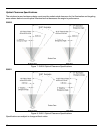
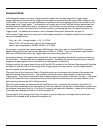
Example 2: Snapshot mode with Illumination being forced on for a given duration after which FirstFlash
circuitry takes over (see figure below).
= Denotes the actual duration of LED light will be determined by the FirstFlash circuitry. The
duration will vary based on object, object distance, and ambient light conditions.
Figure 11. Example 2