


5
Mounting Specifications
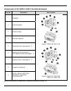
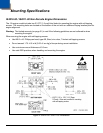
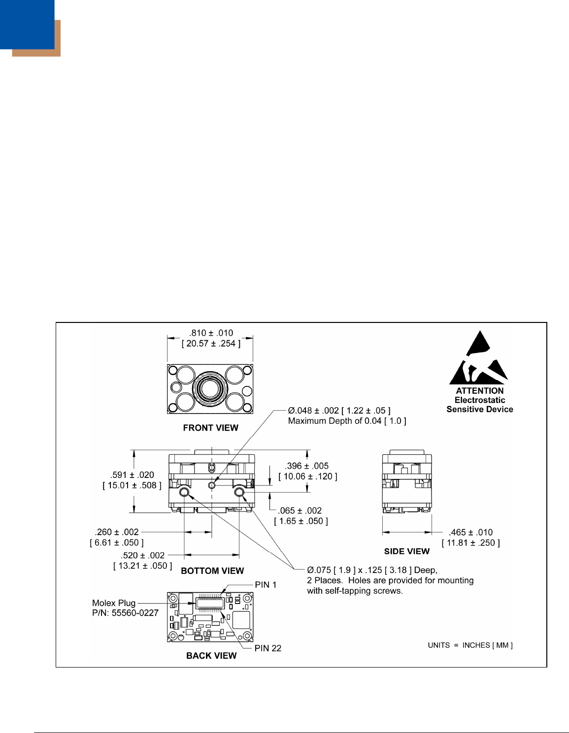
IS4910-00 / IS4911-00 Non-Decode Engine Dimensions
The -00 engine model includes two Ø .075" [1.9 mm] blind holes for mounting the engine with self-tapping
screws. The mounting holes are located on the bottom of the unit with an additional keying location point for
engine alignment.
Warning: The limited warranty (on page 31) is void if the following guidelines are not adhered to when
mounting the engine.
When securing the engine with self-tapping screws:
• Use M2.2 x 4.5 Philips pan head, type AB, Steel, zinc clear, Trivalent self-tapping screws.
• Do not exceed 1.75 +0.5 in-lb [2.02 +6 cm-kg] of torque during screw installation.
• Use a minimum mount thickness of 0.3 mm.
• Use safe ESD practices when handling and mounting the engine.
Figure 4. IS4910-00 / IS4911-00 Dimensions