


19
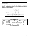
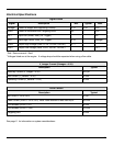
Electrical Specifications
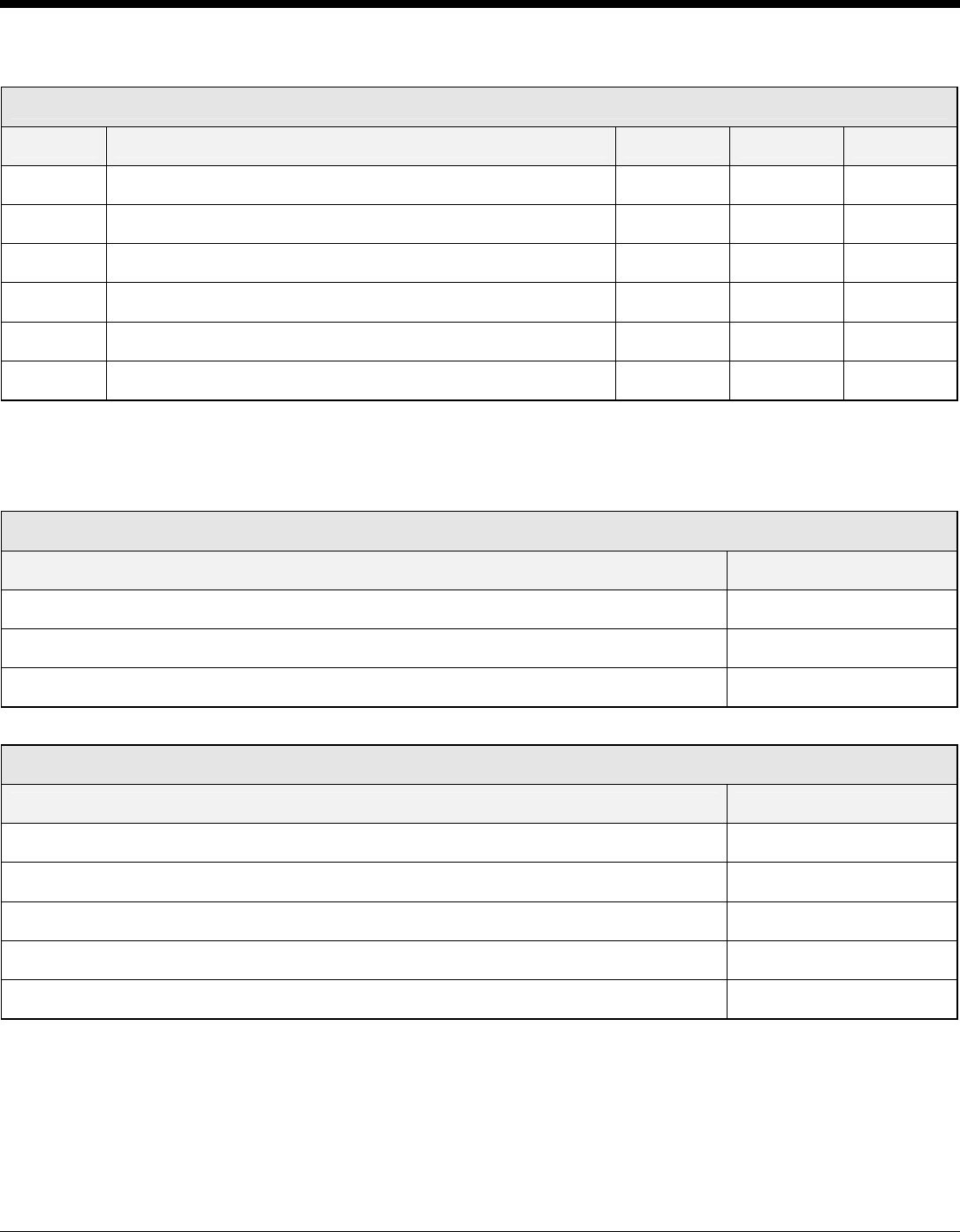
Signal Levels
Signal Description Min. Typical Max.
Vimager Power to Imager and Supporting Circuitry 3.1V 3.3V 3.5V
VLED Power to Illumination and Targeting LEDs 3V - 5.5V
VIL1 Input Low (Aimer, Illum_On, Trigger) .6V
VIH1 Input High (Aimer, Illum_On, Trigger) 2.1V Vimager
VOH2 Output High Voltage (Data, PCLK, VSYNC, HSYNC) 2.71
VOL2 Output Low Voltage (Data, PCLK, VSYNC, HSYNC) .3V1
1
Sink / Source current = 2mA
2
Voltages listed are at the engine. A voltage drop should be expected when using a flex cable.
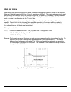
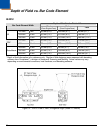
V_Imager Current (Vimager = 3.3V)
Description Typical
Stand By Current (V_imager = 3.3V) 450 µA
Idle Current (V_camera = 3.3V) 55 mA
Operating Current (V_camera = 3.3V) 90 mA
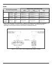
VLED Current
Description Typical
idle (VLED = 5V or 3.3V) 50 µA
Peak Current (VLED = 5V or 3.3V) Note: Peak duration of less than 20µS 350 mA
LED enabled (VLED = 5V) 90 mA
LED enabled (VLED = 3.3V) 155 mA
Targeting LED 24 mA
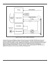
See page 11 for information on system considerations.