


HONEYWELL Aerospace Electronic Systems Page 22
Use or disclosure of information on this page is subject to the restrictions on the title page of this document.
• Maintenance Memory Integrity: Verify that faults that are written to the maintenance memory are
correctly retained in memory.
• Over-temperature Monitor: Monitor internal LRU temperature and log a fault if normal operational
temperature limits are exceeded.
• Interface Tests: Verify physical connections, wiring, and input and output circuitry.
• Network Subsystem Test: Verify availability and status of equipment on networks and busses.
Depending on the severity of the fault and the effect on system performance, the fault may be annunciated
to the flight crew as a system failure. Maintenance personnel may extract faults from the unit through
several methods:
• The datalink display allows for display and extraction of unit fault storage.
• The front panel LEDs display LRU faults.
• Faults may be downloaded to a Portable Data Loader (PDL) for data analysis.
• Faults may be loaded onto a PC via the Debug and Maintenance Terminal function.
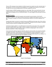
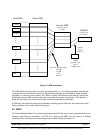
APM
The APM contains information regarding the install status of the various
communications links (VHF, UHF, & HF radios, SATCOM, Ethernet, Mode-
S) as well as the install status of various external LRUs (FMC, printer,
CFDIU, ACMS, CVR, ELS, MCDU/MIDU/CDU).
The APM is programmable from the datalink display device via the system
pages (Note: it is also possible to program via a DMT, but Honeywell is not
recommending the DMT as a product the airline operator needs).
Data Loading
The baseline Mark III CMU supports ARINC 615 data loading via the front connector for portable dataloading,
through the rear connector for ADL processing or via PCMCIA memory cards through the front of the unit.
ARINC 615A (Ethernet) data-loading is planned future enhancements.
3.2 Growth Functionality
VDL Mode 2
Communications over the VHF subnetwork is the most standard method of transmitting datalink messages.
It is expected that today’s 2.4kbps networks will start to have significant congestion problems in the future,
and to avoid this, a new network is being introduced to avoid this problem. This new network being VDL
mode 2. It should be noted that the existing network will not become disabled when VDL mode 2 comes on-
line, but is expected to remain viable for at least another ten years. There are also other changes that are
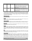
being proposed for future VHF network enhancements. The following table describes the various progression
of VHF datalink modes:
VDL Mode Modulation Medium Access Notes
0 MSK CSMA Allows existing MUs to interface with a VDR using the
ACARS Subnetwork at 2.4 kbps. The VDR is in effect
acting as if it were an ARINC 716 analog radio.
A MSK CSMA Allows CMUs to interface with a VDR using the ACARS
VHF Subnetwork at 2.4 kbps. The VDR output to the
ground is the old ACARS style, but the VDR interface
with the CMU is digital.
2 D8PSK CSMA Allows CMUs to interface with a VDR using a digital
interface, and adds new protocols within VHF radios and
CMUs to support operation over VHF Subnetwork at 31.5
Honeywell APM