


HONEYWELL Aerospace Electronic Systems Page 49
Use or disclosure of information on this page is subject to the restrictions on the title page of this document.
• Patented multi-layer microstrip/fiberglass high reliability printed wiring board (PWB
• Analog Output Discretes
• PCI BUS-based Connector
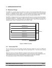
5.1.5 Spare CCAs (Growth)
The MARK III provides two CCA growth slots for expansion. The growth slots may be used to provide an
integrated VHF Data Radio (VDR) into the MARK III, memory expansion to allow the CMU to act as an
aircraft file server, or other product variants.
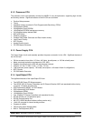
Minimum features of the Spare CCAs are:
• PCI BUS-based Connector.
• BITE Circuitry.
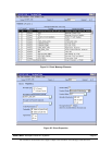
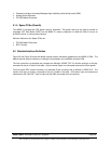
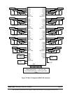
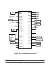
5.2 Detailed Interface Definition
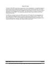
Figure 32 and Figure 33 show the default external system interfaces supported by the MARK III CMU. The
default external system interfaces, including the bus speeds, are modifiable using the APM.
The rear connector is a standard unit connector as defined in ARINC 758. The function and type of circuitry
connected to the pin is listed in the table. All pins named ‘Spare’ are Honeywell reserved for future growth.
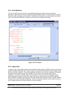
The front panel PDL circular connector is a standard 53-pin connector that is defined in ARINC 615. The
function and type of circuitry connected to the pin is listed in the table. All function input and outputs are
referenced to the CMU (DLT Input is input into the CMU and output from the terminal).