


WEB-700 WEB-700-O CP-700
95-7776—03 12
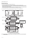
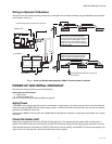
OPTION CARD COM PORT ASSIGNMENTS
COM port assignments for option cards installed in a WEB/CP-700 start at COM5, with Slot 1 evaluated first, then Slot 2. (COM1
and COM2 are always assigned to the onboard RS-232 and RS-485 ports, while COM3 and COM4 are reserved for slots.)
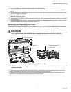
INSTALLING AN OPTION CARD
For option-specific details, see the mounting & wiring document that accompanies the particular option card. The following
procedure provides a basic set of steps.
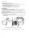
WARNING
Installing an option card in option Slot 2 requires careful attention—you must carefully pry up the shield tab to
install the option card under the tab. Do not install an option card in Slot 2 with the card resting on top of the
shield tab! Otherwise, an electrical short or some other issue from misaligned card header pins may result.
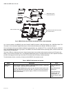
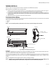
Mounting an option card in a WEB/CP-700.
1. Remove power from the WEB/CP-700, including any external battery—see the previous on page 11.
2. Remove the cover. See Removing and Replacing the Cover, page 9.
3. Remove the blanking plate for the option slot, retaining the two screws. Retain the blanking plate in case the option card
must be removed later.
4. Carefully insert the pins of the option card into the socket headers of the option card slot.
NOTE: If installing in Slot 2, first carefully pry up the shield tab that goes over the standoff. Option card 2 must be
installed under the shield tab.
The mounting holes on the option board should line up with the standoffs on the base board. If they do not, the connec-
tor is not properly aligned. Press until the option card is completely seated.
5. Place the custom end plate for the option card over the connector(s) of the option card. With some option cards, the card’s
end plate is pre-fastened.
6. With the mounting holes aligned with the standoffs, place the two screws through the end plate, and into the standoffs on
the WEB/CP-700 base board. Using a screwdriver, hand tighten these screws.
7. Replace the cover on the controller.
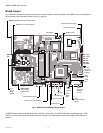
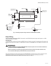
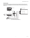
About Remote I/O Modules
The WEB/CP-700 has an integral 6-pin connector to support remote I/O modules. The connector provides both 15Vdc power and
RS-485 communications to modules on that connected trunk, and is located on the right side of the unit.
Each remote I/O module has a DIN-mount base, and provides two (2) 6-pin connectors that allow you to “chain” multiple modules
together into one assembly. Table 3. lists the currently available modules.
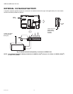
About MiniPCI Cards
The WEB/CP-700 has one (1) available MiniPCI slot—see Fig. 5, page 10. This slot supports a specific 802.11 wireless (Wifi)
adapter option, model NPB-WIFI-7.
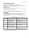
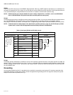
Table 3. Remote I/O modules compatible with the WEB/CP-700
Model Description Notes
IO-16-REM-
H
Remote I/O RS-485 Module
DIN-mountable RS-485 comm
module that provides 16 points I/O,
with I/O point types as noted.
Provides the following I/O points:
• 8 - Universal Inputs (UIs).
• 4 - Digital Outputs (DOs), SPST-relay type.
• 4 - Analog Outputs, 0–10Vdc type.
Up to 16 (maximum) IO-16-REM-H accessory modules are
supported.
Wiring is covered in a separate document, see the IO-16-REM-H
Installation and Configuration Instructions.