


WEB-700 WEB-700-O CP-700
19 95-7776—03
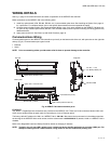
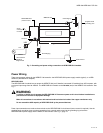
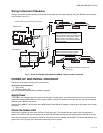
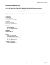
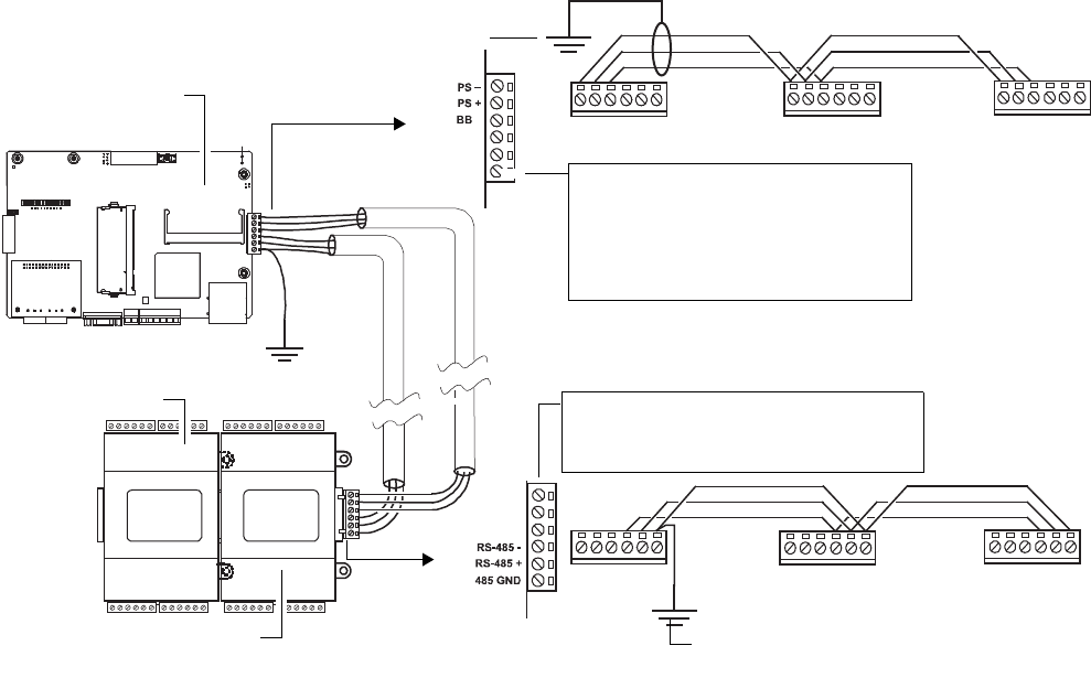
Wiring to Remote I/O Modules
Wiring to remote I/O modules typically provides both 15Vdc power and 12V battery backup, along with RS-485 communications
to the modules. See Fig. 11.
Fig. 11. Power and RS-485 cabling between WEB/CP-700 and remote I/O modules
POWER UP AND INITIAL CHECKOUT
Following all mounting and wiring, perform the following:
Initial power up and checkout.
1. Apply Power.
2. Check the Status LED.
Also see the section About the Backup Batteries, page 20.
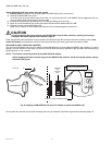
Apply Power
The WEB/CP-700 controller does not include an on/off switch. To apply power, you simply energize the AC circuit (90–263 Vac)
wired to the attached NPB-PWR-UN-H power supply module. If remote I/O modules are wired to the unit, they are also typically
powered by the WEB/CP-700 as well.
If powering the WEB/CP-700 controller with a NPB-WPM-US (Wall Mount AC Adapter), simply plug the AC adapter into a nearby
wall outlet.
Check the Status LED
When power is applied, the front cover STATUS LED will light green. This indicates that the system is OK and that power is
applied. The STATUS LED may be blinking until the QNX OS has finished loading and the Niagara platform daemon is running.
Once this boot sequence has finished, the STATUS LED should remain lit (steady), and the BEAT LED should start blinking, at a
typical rate of 1Hz. Typically, this is about 30 seconds after power is applied.
WEB/CP-700
IO-16-REM-H
IO-16-REM-H
Connect shield wire to ground at one end only
Connect RS-485 shield wire to ground at
one end only
Power Supply (15V) and 12V Backup
Battery is routed to remote IO modules using
a 3-conductor with shield cable. Use the
shortest wiring route possible for power
wiring—star, tee, bus, and loop topologies
are all permissible.
RS-485 communications must be “daisy-
chained” to remote IO modules using a
separate shielded twisted-pair cable.