


WEB-700 WEB-700-O CP-700
95-7776—03 8
Physical Mounting
The following information applies about physically mounting the unit.
• You can mount the WEB/CP-700 in any orientation. It it not necessary to remove the cover before mounting.
• Mounting on a 35mm wide DIN rail is recommended. The WEB/CP-700 unit base has a molded DIN rail slot and locking clip,
as does the NPB-PWR-UN-H power supply module and any I/O expansion modules. Mounting on a DIN rail ensures accurate
alignment of connectors between all modules.
• If DIN rail mounting is impractical, use screws in mounting tabs on the NPB-PWR-UN-H module and the WEB/CP-700, as well
as any end-connected accessory. Tab mounting dimensions are on the last page of this document.
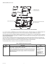
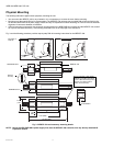
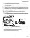
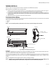
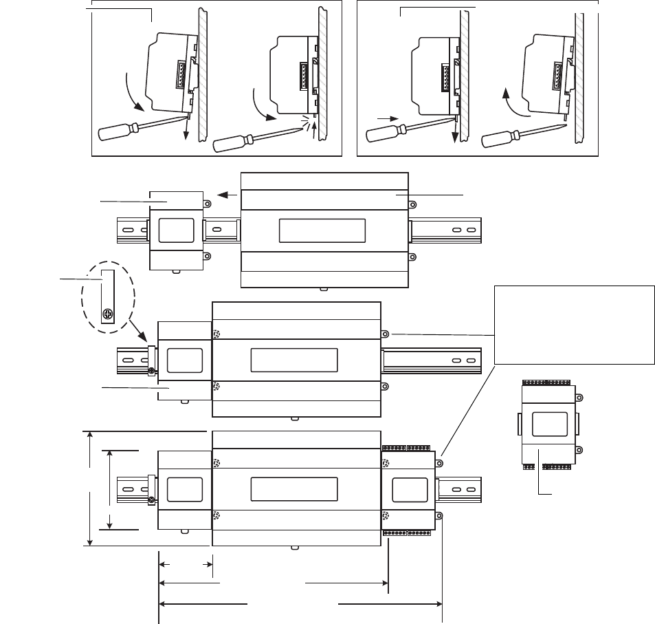
Fig. 3 and the following procedure provides step-by-step DIN rail mounting instructions for the WEB/CP-700.
Fig. 3. WEB/CP-700 and accessory mounting details.
NOTE: Mount the NPB-PWR-UN-H power supply first, then the WEB/CP-700 controller, then any directly attached I/O
expansion module.
4.1" (104)
5.6"
(142)
3.46"
(88)
11.75" (298)
15.125" (384)
Mounting on
DIN rail
Removing from DIN rail
NPB-PWR-UN-H
DIN rail
end clip
NPB-PWR-UN-H
IO-16-REM-H
WEB/CP-700
Secure controller or last directly
attached I/O module using either
screws or DIN rail end clip (if end
clip does not interfere with 6-
position end connector).