


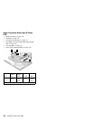
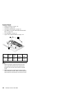
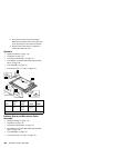
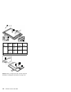
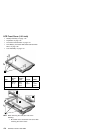

System Board
“Battery Assembly” on page 142
“Keyboard” on page 145
“Processor Thermal Plate” on page 147
“RTC Battery, Processor EMI Shield and Hard Disk
Drive” on page 148
“LCD Assembly” on page 151
“Upper Cover (Keyboard Bezel)” on page 153
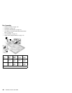
2
1
4
3
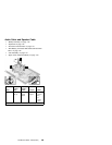
Notes:
1. When removing the system board from the base
cover, gently raise the side of the system board
facing the rear I/O ports; then pull out the system
board.
2. When replacing the system board, align the power
switch and power actuator. Make sure that the power
switch operates correctly before securing the screws.
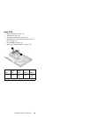
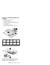
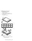
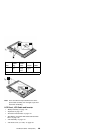
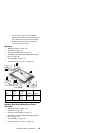
Step
Size
(Quan-
tity)
Head &
Color Torque Memo
1 M2.5 x
6L (2)
Bind
head,
black
3.2
kgf-cm
w/
nylock
paste
Note: Make sure you use the correct screw for replacement.
166 ThinkPad i Series 1400 HMM