


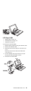
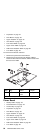
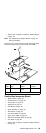
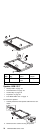
“Power Latch, IR Board, and DC-DC & BATT Board”
on page 63
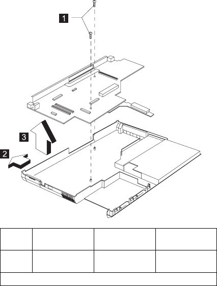
Note: See “Replacing the System Board” on page 48
before proceeding.
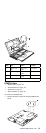
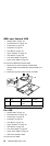
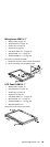
Remove the two screws from the planar board and gently
remove the planar board from the base cover ASM.
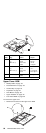
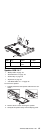
Step
Size (Quan-
tity)
Head &
Color Torque
1 M2.5 x 6L (2) Pan head,
black
3.2 kgf-cm
Note: Make sure you use the correct screw for replacement.
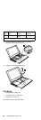
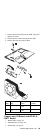
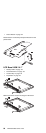
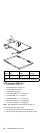
Combo Bay Interposer Board
“Battery ASM” on page 49
“Hard Disk Drive” on page 49
“Combo Bay” on page 50
“Keyboard” on page 54
“LED Board” on page 56
“Upper Heatsink” on page 56
“CPU Board” on page 58
“LCD Panel ASM” on page 59
“Upper Cover ASM” on page 60
“IMM Lower Heatsink ASM” on page 62
“Fan ASM” on page 62
“Power Latch, IR Board, and DC-DC & BATT Board”
on page 63
ThinkPad 390/i Series 1700
65