Front panel
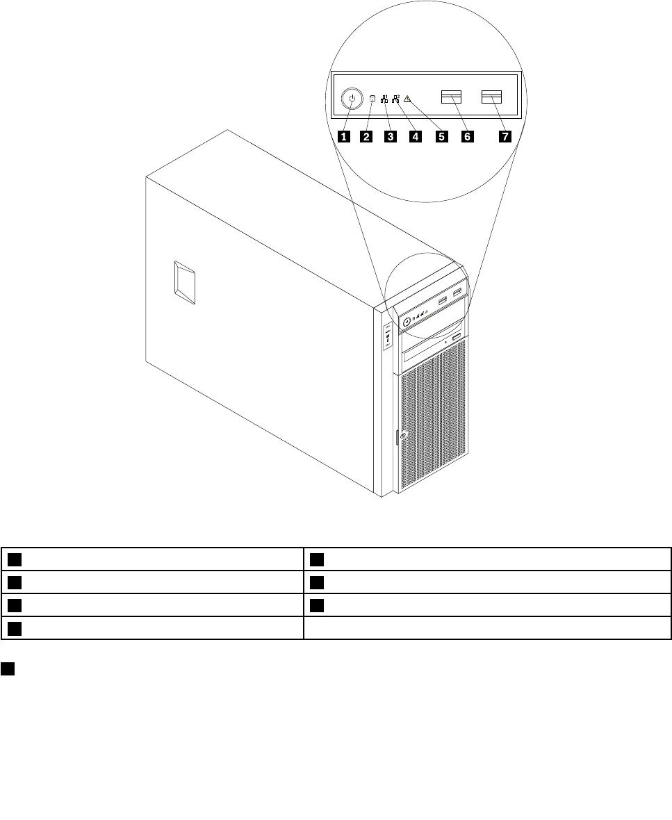
This topic provides information to help you locate the control, connectors, and LEDs on the front panel of
the server.
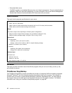
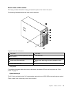
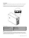
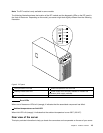
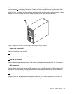
The following illustration shows the control, connectors, and LEDs on the front panel of the server.
Depending on the model, your server might look slightly different from the following illustration.
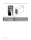
Figure 4. Front panel
1 Power switch with power status LED
5 System status LED
2 Hard disk drive status LED
6 Front USB connector 1
3 Network Interface Controller (NIC) 1 status LED 7 Front USB connector 2
4 NIC 2 status LED
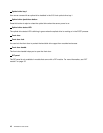
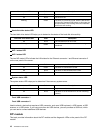
1 Power switch with power status LED
You can press the power switch to turn on the server when you nish setting up the server. You can also
hold the power switch for several seconds to turn off the server if you cannot turn off the server from the
operating system. See Chapter 4 “Turning on and turning off the server” on page 53
. The power status LED
helps you to determine the current power status.
Chapter 3. Product overview 17


