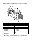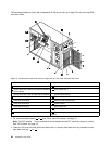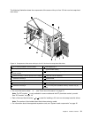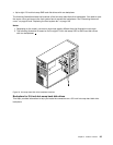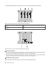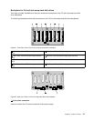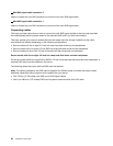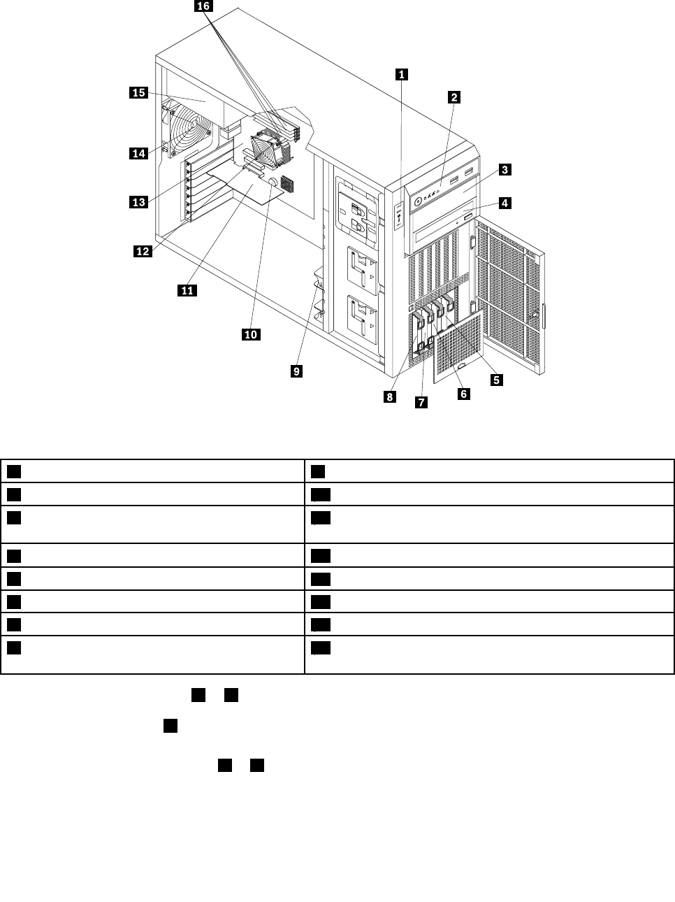
The following illustration shows the components of the server with up to four 3.5-inch non-hot-swap hard
disk drives.
Figure 14. Components of the server with up to four 3.5-inch non-hot-swap hard disk drives
1 DIT module (available in some models)
9 Front system fan 1
2 Front panel
10 System board battery
3 Optical drive bay 2 (with an optical drive installed
in some models)
11 Expansion card (varies by model)
4 Optical drive bay 1 (with an optical drive installed)
12 Heat sink and fan assembly
5 Hard disk drive bay 3
13 System board
6 Hard disk drive bay 2
14 Rear system fan
7 Hard disk drive bay 1 15 Power supply
8 Hard disk drive bay 0
16 Four memory slots (installed memory modules vary by
model)
• For more information about 1 to 4 , see “Front view of the server” on page 15.
Note: The DIT module 1 is only available in some models and the DIT panel also varies by model.
See “DIT module” on page 18.
• Each of the hard disk drive bay ( 5 to 8 ) is used for installing a 3.5-inch non-hot-swap hard disk drives.
Note: The number of the installed hard disk drives varies by model.
• For information about the supported expansion card, see “System board components” on page 42.
Chapter 3. Product overview 31


