


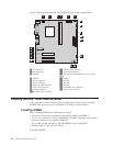
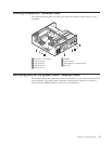
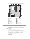

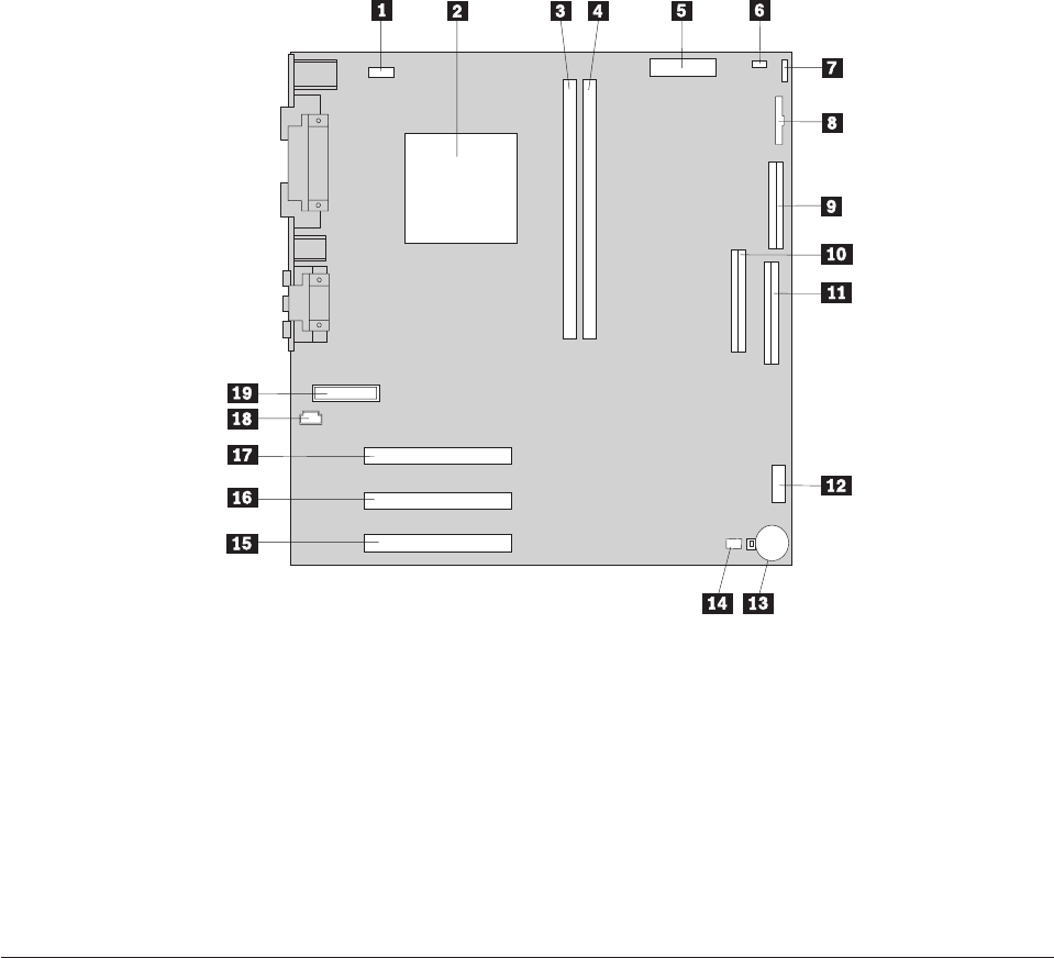
See the following illustration for the location of parts on the system board.
1 Fan connector 11 Primary IDE connector
2 Microprocessor 12 Front USB connector
3 DIMM 1 13 Virtual clear CMOS/BIOS recovery jumper
4 DIMM 2 14 Battery
5 Power connector 15 PCI slot
6 Power connector 16 PCI slot
7 Hard disk LED connector 17 PCI slot
8 Power LED connector 18 CD-ROM audio connector
9 Diskette connector 19 Front panel connector
10Secondary IDE connector
Installing memory - desktop model
Your computer has two connectors for installing dual in-line memory modules
(DIMMs) that provide up to a maximum of 512 MB of system memory.
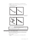
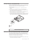
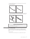
Installing DIMMs
When installing DIMMs, the following rules apply:
v Fill each system memory connector sequentially, starting at DIMM 1
v Use 3.3 V, synchronous, 168-pin, unbuffered, 133 MHz nonparity synchronous
dynamic random access memory (SDRAM)
v Use 32 MB, 64 MB, 128 MB, or 256 MB DIMMs in any combination
v DIMM heights of 38.1 mm (1.5 inches)
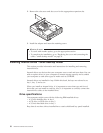
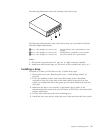
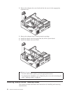
To install a DIMM:
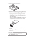
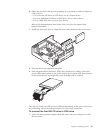
1. Remove the cover. See “Removing the cover - desktop model” on page 34.
36 Hardware Maintenance Manual