


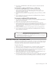

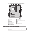
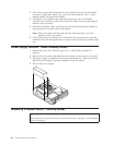
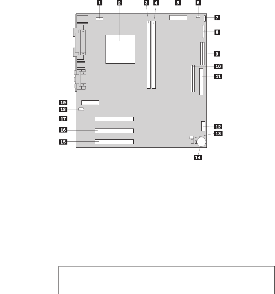
See the following illustration for the location of parts on the system board.
1 Fan connector 11 Primary IDE connector
2 Microprocessor 12 Front USB connector
3 DIMM 1 13 Virtual clear CMOS/BIOS recovery jumper
4 DIMM 2 14 Battery
5 Power connector 15 PCI slot
6 Power connector 16 PCI slot
7 Hard disk LED connector 17 PCI slot
8 Power LED connector 18 CD-ROM audio connector
9 Diskette connector 19 Front panel connector
10Secondary IDE connector
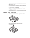
Replacing a System Board - Small Desktop Model
Important:
Before replacing a system board, back up Asset information by using the “Asset EEPROM
backup” on page 16.
60 Hardware Maintenance Manual