


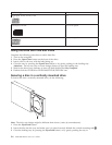

Drive
controls
and
connectors
The
following
diagrams
show
the
location
and
functions
of
the
drive
controls
and
connectors.
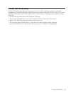
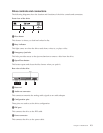
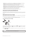
Front
view
of
the
drive
RECORDER
MULTIM U LTI
1Disc
drawer
This
drawer
is
where
you
load
and
unload
a
disc.
2Busy
indicator
This
light
comes
on
when
the
drive
reads
from,
writes
to,
or
plays
a
disc.
3Emergency
eject
hole
This
hole
provides
access
to
the
eject
mechanism
to
remove
a
disc
from
the
drive.
4Open/Close
button
This
button
opens
and
closes
the
disc
drawer
when
you
push
it.
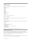
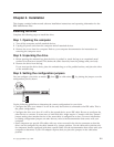
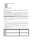
Rear
view
of
the
drive
Pin 1
1Reserved
2Audio-out
connector
This
connector
transmits
the
analog
audio
signals
to
an
audio
adapter.
3Configuration
pins
These
pins
are
used
to
set
the
drive
configuration.
4IDE
port
This
connects
the
drive
to
the
IDE
cable.
5Power
connector
This
connects
the
drive
to
the
power
cable.
Chapter
1.
Introduction
1-3