


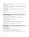

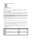
If
you
place
the
jumper
in
the
cable-select
position,
the
IDE
cable
automatically
assigns
the
master
and
slave
settings
based
on
the
position
of
the
drive
on
the
cable.
You
must
use
the
cable-select
setting
for
this
cabling
system
whether
the
drive
is
the
only
device
or
the
second
device
connected
to
the
cable.
The
drive
closest
to
the
IDE
controller
is
automatically
the
master
drive.
Any
other
devices
on
the
IDE
cable
must
also
be
set
to
cable-select.
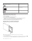
Step
4.
Mounting
the
drive
in
the
bay
Attention
Be
sure
to
use
the
M3
x
5-mm
mounting
screws
in
the
option
package
when
securing
screws
directly
into
the
drive.
Using
screws
that
are
too
long
might
damage
the
drive.
You
can
mount
the
drive
horizontally
or
vertically
in
the
computer.
If
you
mount
the
drive
vertically,
you
must
secure
any
discs
that
you
place
into
the
drive
before
the
drive
tray
is
closed,
or
the
drive
will
not
be
able
to
read
the
disc
properly.
1.
Slide
the
drive
into
the
bay.
Your
computer
might
have
required
procedures
for
installing
storage
devices.
For
more
information
on
storage
devices,
refer
to
the
documentation
that
comes
with
your
computer.
2.
Align
the
drive-bay
screw
holes
with
the
threaded
holes
in
the
drive
housing
or
mounting
bracket.
3.
Thread
the
screws
in
loosely
to
check
their
position.
Two
screws
are
usually
used
on
each
side.
Verify
that
the
alignment
is
correct;
then
tighten
the
screws
to
secure
the
drive.
Do
not
overtighten.
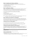
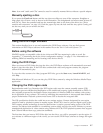
Step
5.
Attaching
the
cables
to
the
drive
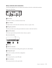
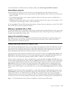
The
following
diagram
shows
where
to
connect
the
cables
to
the
drive.
1.
Attach
a
40-pin
IDE-cable
connector
1to
the
IDE
connector
on
the
drive.
Align
the
cable
so
that
the
color-coded
edge
is
closest
to
the
power
cable
connector
2.
Use
the
80-conductor
high
speed
IDE
cable
that
is
provided
with
this
option
if
there
is
no
cable
attached
to
the
IDE
port,
if
there
is
only
one
device
connector
on
the
computer
IDE
cable,
or
if
the
existing
cable
in
your
computer
is
a
low-speed
40-conductor
type.
The
IDE
cable
can
have
up
to
three
connectors.
For
the
best
signal
quality
when
you
are
connecting
only
one
device
to
the
IDE
cable,
connect
one
end
of
the
cable
to
the
IDE
port,
and
connect
the
other
end
of
the
cable
to
the
device.
Do
not
use
the
middle
connector.
If
you
are
connecting
two
devices
to
the
IDE
cable,
connect
one
end
of
the
cable
to
the
IDE
port,
and
connect
the
master
and
slave
devices
to
the
remaining
connectors
on
the
other
end.
Many
computers
have
two
cables
for
attaching
up
to
four
ATA
devices.
For
best
performance,
attach
fast
devices
(hard
disk
drives)
to
the
cable
that
is
connected
to
the
primary
IDE
port,
and
connect
the
drive
or
other
slower
devices
(CD-ROM
drives,
tape
drives,
diskette
drives)
to
the
cable
that
is
connected
to
the
secondary
IDE
port.
2.
Attach
a
four-pin
power
cable
2to
the
power
connector
on
the
drive.
Be
sure
that
the
cables
will
not
be
pinched
or
crowded
by
the
computer
cover
and
that
all
other
cable
and
power
connections
are
secure.
2-2
IBM
Multi-Burner
Plus
User’s
Guide