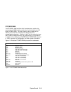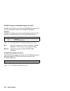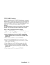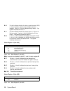
Bits 6–5 If these bits are a pattern of 01, the oscillator is turned
on and the RTC is allowed to keep time. The next
update will occur at 500 ms after a pattern of 01 is
written to these bits.
Bits 4 To use the original bank of memory, select 0. To use
the extended registers, select 1.
Bits 3–0 These bits allow the selection of a divider output
frequency or disable the divider output.
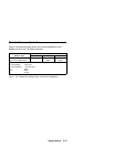
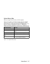
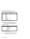
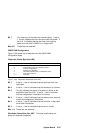
Status Register B (Hex 00B)
Figure 2-17. Status Register B (Hex 00B)
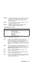
Bit Function
7 Set
6 Enable periodic interrupt
5 Enable alarm interrupt
4 Enable update-ended interrupt
3 Enable square wave
2 Date mode
1 24-hour mode
0 Enable daylight-saving time
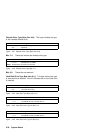
Bit 7 If set to 0, this bit updates the cycle, normally by
advancing the count at a rate of one cycle per second. If
set to 1, it immediately ends any update cycle in
progress, and the program can initialize the 14 time bytes
without any further updates occurring until this bit is set
to 0.
Bit 6 This is a read/write bit that allows an interrupt to occur at
a rate specified by the rate and divider bits in status
register A. If set to 1, this bit enables the interrupt. The
system initializes this bit to 0.
Bit 5 If set to 1, this bit enables the alarm interrupt. The
system initializes this bit to 0.
Bit 4 If set to 1, this bit enables the update-ended interrupt.
The system initializes this bit to 0.
Bit 3 If set to 1, this bit enables the square-wave frequency as
set by the rate-selection bits in status register A. The
system initializes this bit to 0.
System Board 2-23


