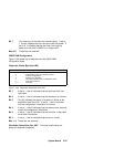
Bit 7 This read-only bit monitors the internal battery. If set to
1, this bit indicates that the real-time clock has power. If
set to 0, it indicates that the real-time clock has lost
power and the data in CMOS is no longer valid.
Bits 6–0 These bits are reserved.
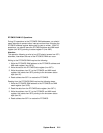
CMOS RAM Configuration
Figure 2-20 shows the bit definitions for the CMOS RAM
configuration bytes.
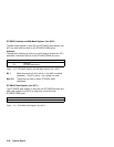
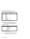
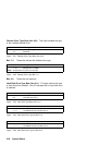
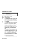
Diagnostic Status Byte (Hex 00E)
Figure 2-20. Diagnostic Status Byte (Hex 00E)
Bit Function
7 Real-time clock power
6 Configuration record and checksum status
5 Incorrect configuration
4 Memory size mismatch
3 Hard disk controller/drive C initialization status
2 Time status indicator
1, 0 Reserved
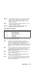
Bit 7 If set to 1, this bit indicates that the real-time clock has
lost power.
Bit 6 If set to 1, this bit indicates that the checksum is incorrect.
Bit 5 This bit indicates the results of a power-on check of the
equipment byte (hex 014). If set to 1, this bit indicates
that the configuration information is incorrect.
Bit 4 If set to 1, this bit indicates that the memory size does not
match the configuration information.
Bit 3 If set to 1, this bit indicates that the controller or hard disk
drive failed initialization.
Bit 2 If set to 1, this bit indicates that the time is invalid.
Bits 1, 0 These bits are reserved.
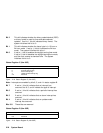
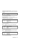
Shutdown Status Byte (Hex 00F):
This byte is defined by the
power-on diagnostic programs.
System Board 2-25


