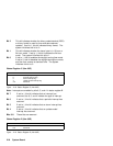
Bit 2 This bit indicates whether the binary-coded-decimal (BCD)
or binary format is used for time-and-date calendar
updates. If set to 1, this bit indicates binary format. The
system initializes this bit to 0.
Bit 1 This bit indicates whether the hours byte is in 12-hour or
24-hour mode. If set to 1, this bit indicates the 24-hour
mode. The system initializes this bit to 1.
Bit 0 If set to 1, this bit enables the daylight-saving-time mode.
If set to 0, this bit disables the daylight-saving-time mode,
and the clock reverts to standard time. The system
initializes this bit to 0.
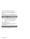
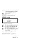
Status Register C (Hex 00C)
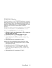
Figure 2-18. Status Register C (Hex 00C)
Bit Function
7 Interrupt request flag
6 Periodic interrupt flag
5 Alarm interrupt flag
4 Update-ended interrupt flag
3–0 Reserved
Note: Interrupts are enabled by bits 6, 5, and 4 in status register B.
Bit 7 If set to 1, this bit indicates that an interrupt has
occurred; bits 6, 5, and 4 indicate the type of interrupt.
Bit 6 If set to 1, this bit indicates that a periodic interrupt has
occurred.
Bit 5 If set to 1, this bit indicates that an alarm interrupt has
occurred.
Bit 4 If set to 1, this bit indicates that an update-ended
interrupt has occurred.
Bits 3–0 These bits are reserved.
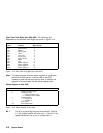
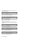
Status Register D (Hex 00D)
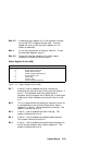
Figure 2-19. Status Register D (Hex 00D)
Bit Function
7 Valid RAM
6–0 Reserved
2-24 System Board


