


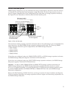
Configuring the drive loops
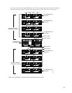
The procedure and illustrations in this section show how to connect one group of four storage expansion
enclosures in a redundant drive loop. Instructions for how to connect a second group of four storage
expansion enclosures in a redundant drive loop are also included in this procedure.
To complete this procedure, you will need two fiber-optic cables per storage expansion enclosure.
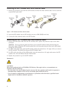
Attention: Handle and install fiber-optic cables properly to avoid degraded performance or loss of
communications with devices. Do not overtighten the cable straps or bend the cables to a diameter of less
than 76 mm (3 in.), or a radius less than 38 mm (1.5 in.).
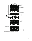
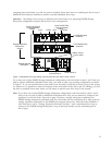
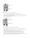
1. Connect the first two storage expansion enclosures to drive loop A, as shown in Figure 9 on page 11.
Starting with the first storage expansion enclosure, connect a fiber-optic cable from the In port on the
left environmental services module (ESM) board to the Out port on the left ESM board in the second
(next) storage expansion enclosure.
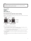
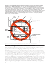
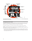
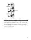
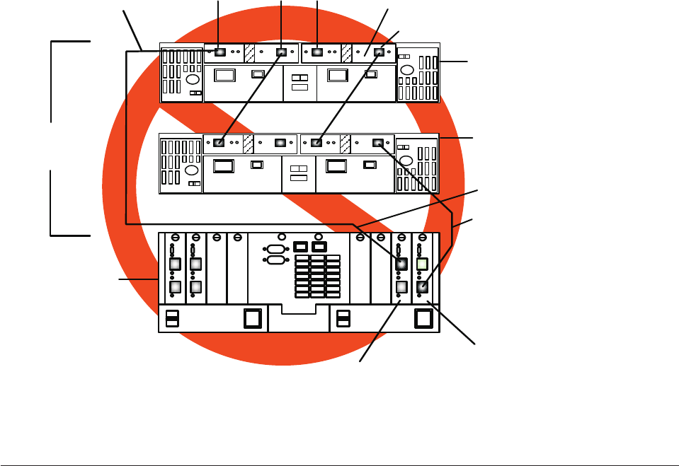
Drive Loop A
Drive Loop B
Drive Loop A Fibre
Channel interface
Cables
Drive Loop B Fibre
Channel interface
Cables
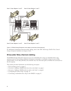
First DS4000 drive
enclosure
Last DS4000 drive
enclosure
Storage Expansion
Enclosures -
Group 1
DS4500 Storage
Subsystem
Input
Input
Output
Output
Drive minihub 1
Drive minihub 2
ds452min
Figure 8. Redundant drive loop cabling overview with two mini hubs in slots 1 and 2 — Not for use unless you meet
the requirements in the above Note
10