


swapping these mini-hubs, you will not need to schedule down time later for re-cabling the drive loop if
additional mini hubs are installed to enable a second redundant drive loop.
Attention: Re-cabling of drive loops to different drive mini hubs in an operating DS4500 Storage
Subsystem configuration requires down time for the configuration.
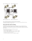
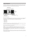
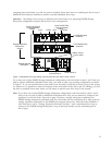
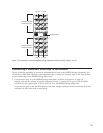
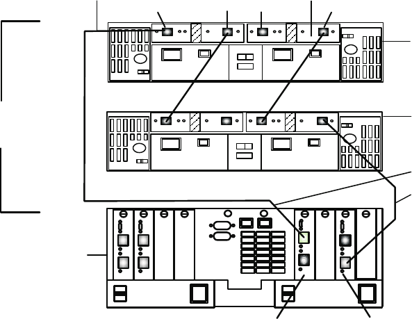
If you have an existing DS4500 Storage Subsystem configuration with mini hubs in slots 1 and 2 and you
plan to add an additional redundant drive loop, you must re-cable your existing configuration as shown
in Figure 7. If you can schedule down time before you are ready to add the new drive loop in the system
(or whenever it is possible to make the changes to the mini hubs and the drive side FC cabling), you will
not have to schedule down time when you are ready to add the new drive loop in the system.
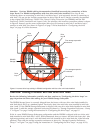
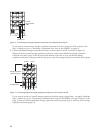
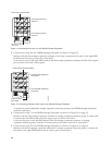
Note: If you have an existing DS4500 Storage Subsystem configuration with mini hubs in slots 1 and 2,
and you do not plan to add an additional redundant drive loop, do not make any changes to the
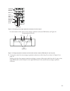
positions of your mini hubs. Figure 8 on page 10 shows a storage subsystem containing one
DS4500 Storage Subsystem populated with two mini hubs and one redundant drive loop with two
storage expansion enclosures, as the DS4500 was shipped previously, with mini hubs installed in
mini hub slots 1 and 2. “Storage Expansion Enclosure Group 1” uses a redundant drive loop to
connect to the DS4500 Storage Subsystem. Loop A and loop B make up one redundant pair of
drive loops.
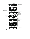
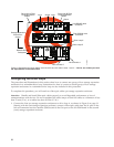
Drive Loop A
Drive Loop B
Drive Loop A Fibre
Channel interface
Cables
Drive Loop B Fibre
Channel interface
Cables
First DS4000 drive
enclosure
Last DS4000 drive
enclosure
Storage Expansion
Enclosures -
Group 1
DS4500 Storage
Subsystem
Input
Input
Output Output
Drive minihub 4
Drive minihub 2
ds452minb
Figure 7. Redundant drive loop cabling overview with two mini hubs in slots 4 and 2
9