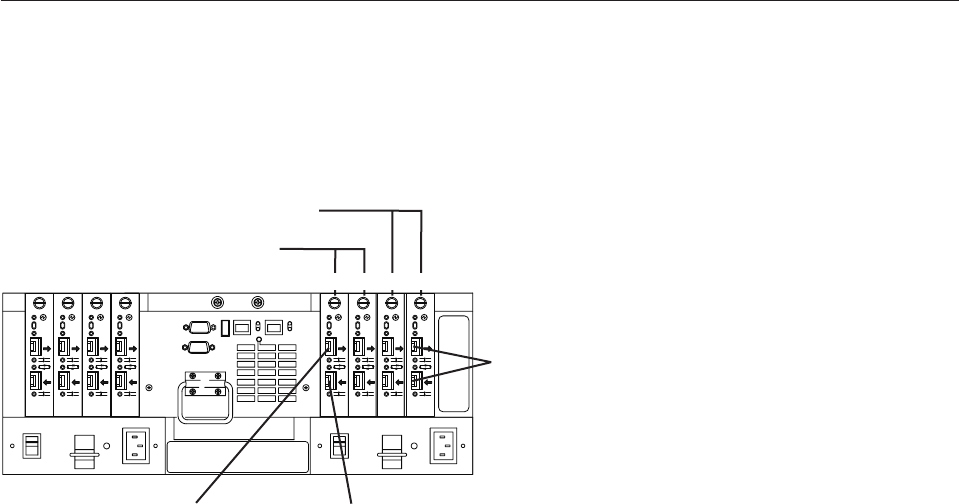
Drive interface ports
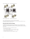
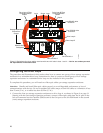
DS4500 Storage Subsystems use only redundant drive-loop configurations. Each drive mini hub connects
to Controller A and Controller B and represents a single drive loop. The drive loops must be set up in
pairs to support redundant drive loop configurations (two data paths per storage expansion enclosure).
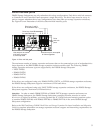
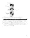
See Figure 4 for an illustration of the drive-side mini-hub interface ports.
The maximum number of storage expansion enclosures that can be connected per pair of redundant drive
loops depends on the IBM DS4000 storage expansion enclosure models used. The following DS4000
storage expansion enclosure types are supported by the DS4500 Storage Subsystem:
v FAStT EXP500
v DS4000 EXP700
v DS4000 EXP710
v DS4000 EXP100
If the drives are configured using only DS4000 EXP700, EXP710, or EXP100 storage expansion enclosures,
the DS4500 Storage Subsystem supports a maximum of 224 hard drives.
If the drives are configured using only FAStT EXP500 storage expansion enclosures, the DS4500 Storage
Subsystem supports a maximum of 220 hard drives.
Attention: In order to attach DS4000 EXP100 or DS4000 EXP710 storage expansion enclosures to a
DS4500 Storage Subsystem, the DS4500 Storage Subsystem controller firmware must be at version
06.xx.xx.xx or higher. In addition, you must purchase the FC/SATA Enclosure Intermix premium option
to combine DS4000 EXP100s with DS4000 EXP700s or DS4000 EXP710s in the same DS4500 Storage
Subsystem configuration.
Refer to the IBM TotalStorage DS4000 Hard Drive and Storage Expansion Enclosure Installation and Migration
Guide for complete information on storage expansion enclosure support and intermixing requirements for
the DS4500 Storage Subsystem.
OUT
IN
!
2 Gb/s
1 Gb/s
2 Gb/s
1 Gb/s
OUT
IN
!
2 Gb/s
1 Gb/s
2 Gb/s
1 Gb/s
OUT
IN
!
2 Gb/s
1 Gb/s
2 Gb/s
1 Gb/s
OUT
IN
!
2 Gb/s
1 Gb/s
2 Gb/s
1 Gb/s
OUTOUT
IN
!
2 Gb/s
1 Gb/s
2 Gb/s
1 Gb/s
OUT
IN
!
2 Gb/s
1 Gb/s
2 Gb/s
1 Gb/s
OUTOUT
IN
!
2 Gb/s
1 Gb/s
2 Gb/s
1 Gb/s
OUT
IN
!
2 Gb/s
1 Gb/s
2 Gb/s
1 Gb/s
Drive
mini-hub
ports
Drive loop C and D
for redundant loop 2
Drive loop A and B
for redundant loop 1
4321
Use one port on each
mini hub to connect
a drive loop cable
Leave one port unoccupied
for future upgrades
d3nu4024
Figure 4. Drive mini-hub ports
5


