


Overview: Cabling a DS4500 with four drive mini hubs
Review the following information carefully and then continue to “Configuring the drive loops” on
page 10 perform the drive-side cabling for your DS4500 Storage Subsystem.
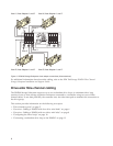
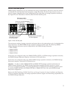
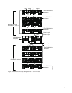
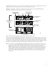
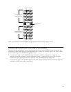
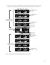
Figure 5 on page 7 shows a storage subsystem containing one DS4500 Storage Subsystem and two
redundant drive loops with four storage expansion enclosures each. The DS4500 configuration shown
requires four drive mini hubs to be installed. Each storage expansion enclosure group uses redundant
drive loops to connect to the DS4500 Storage Subsystem. Loop A and loop B make up one redundant pair
of drive loops, which is labeled “Storage Expansion Enclosures - Group 1.”. Loop C and loop D make up
a second redundant pair, which is labeled “Storage Expansion Enclosures - Group 2.”
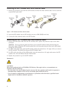
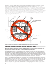
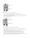
Attention: To prevent loss of storage expansion enclosure redundancy in a DS4500 Storage Subsystem
configuration with four drive mini hubs installed, connect the storage expansion enclosures as shown in
Figure 5 on page 7. Note especially that drive loop B connects to mini hub 2 and drive loop C connects to
mini hub 3.
Note:
The illustrations in this document might differ slightly from the hardware.
6