


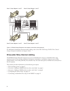
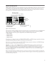
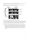
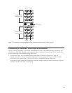
Attention: Previous DS4500 cabling documentation identified incorrectly the connections of drive
loops B and C in DS4500 configurations with four drive mini hubs installed. Drive loop B was
incorrectly shown as connecting to mini hub 3 and drive loop C was incorrectly shown as connecting to
mini hub 2. Do not use the incorrect connections for drive loops B and C that are currently documented
in the original IBM TotalStorage DS4500 Fibre Channel Cabling Instructions (pn 25R0406) and the IBM
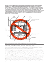
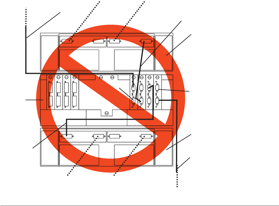
TotalStorage DS4500 Installation and Support Guide. For reference, this incorrect connection scheme is shown
in Figure 6. Instead, use the correct connections (drive loop B connects to mini hub 2 and drive loop C
connects to mini hub 3) as shown in Figure 5 on page 7 and as described in “Configuring the drive
loops” on page 10 of this document.
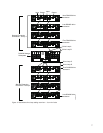
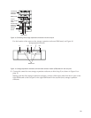
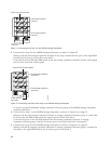
Overview: Cabling a DS4500 with two drive mini hubs
Review the following information carefully and then continue to “Configuring the drive loops” on
page 10 perform the drive-side cabling for your DS4500 Storage Subsystem.
The DS4500 Storage Server is currently shipped from the factory with two drive mini hubs installed in
mini hub slots 4 and 2 as a standard option. Previously, these two mini hubs were installed in mini hub
slots 1 and 2. If the DS4500 Storage Subsystem is shipped with two drive mini hubs installed in mini hub
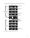
slots 4 and 2, cable the storage expansion enclosures as shown by “Storage Expansion Enclosures - Group
1” in Figure 7 on page 9 using the instructions in “Configuring the drive loops” on page 10
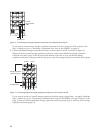
If this is a new DS4500 Storage Subsystem configuration and the DS4500 is shipped with two drive mini
hubs installed in mini hub slots 1 and 2, IBM recommends that you remove the mini hub from slot 1 (the
right most-position) and swap it with the blank mini hub inserted in drive mini hub slot 4 (the left-most
position). Then cable the storage expansion enclosures as shown by “Storage Expansion Enclosures -
Group 1” in Figure 7 on page 9 using the instructions in “Configuring the drive loops” on page 10. By
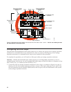
Drive
loop C
Out
Drive loop D
DS4500
Storage Server
In
First storage expansion
enclosure
First storage expansion
enclosure
Drive
loop A
Drive
loop B
ds45cabx
Figure 6. Incorrect drive loop cabling in DS4500 configuration with four drive mini hubs installed
8